
Mechanics of Materials
9th Edition
ISBN: 9780133254426
Author: Russell C. Hibbeler
Publisher: Prentice Hall
expand_more
expand_more
format_list_bulleted
Videos
Textbook Question
Chapter 1.2, Problem 1.1P
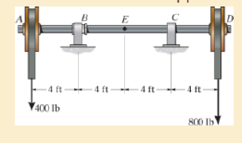
The shaft is supported by a smooth thrust bearing at B and a journal bearing at C. Determine the resultant internal loadings acting on the cross section at E.
Expert Solution & Answer
Want to see the full answer?
Check out a sample textbook solution
Students have asked these similar questions
Repeat Problem 28, except using a shaft that is rotatingand transmitting a torque of 150 N * m from the left bearing to the middle of the shaft. Also, there is a profile keyseat at the middle under the load.
(I want to understand this problem)
Prob 2.
The material distorts into the dashed position
shown. Determine the average normal strains &x, Ey
and the shear strain Yxy at A, and the average
normal strain along line BE.
50 mm
B
200 mm
15 mm
30 mm
D
ΕΙ
50 mm
x
A
150 mm
F
Prob 3.
The triangular plate is fixed at its base, and its apex
A is given a horizontal displacement of 5 mm.
Determine the shear strain, Yxy, at A.
Prob 4.
The triangular plate is fixed at its base, and its apex
A is given a horizontal displacement of 5 mm.
Determine the average normal strain & along the x
axis.
Prob 5.
The triangular plate is fixed at its base, and its apex
A is given a horizontal displacement of 5 mm.
Determine the average normal strain &x along the x'
axis.
x'
45°
800 mm
45°
45%
800 mm
5 mm
Chapter 1 Solutions
Mechanics of Materials
Ch. 1.2 - In each case, explain how to find the resultant...Ch. 1.2 - Determine the resultant internal normal force,...Ch. 1.2 - Determine the resultant internal normal force,...Ch. 1.2 - Determine the resultant internal normal force,...Ch. 1.2 - Determine the resultant internal normal force,...Ch. 1.2 - Determine the resultant internal normal force,...Ch. 1.2 - Determine the resultant internal normal force,...Ch. 1.2 - The shaft is supported by a smooth thrust bearing...Ch. 1.2 - Determine the resultant internal normal and shear...Ch. 1.2 - 1-3. The beam AB is fixed to the wall and has a...
Ch. 1.2 - The shaft is supported by a smooth thrust bearing...Ch. 1.2 - 1-5. Determine the resultant internal loadings in...Ch. 1.2 - 1-6. Determine the normal force, shear force, and...Ch. 1.2 - 1-7. The cable will fail when subjected to a...Ch. 1.2 - *1-8. Determine the resultant internal loadings on...Ch. 1.2 - 1-9. Determine the resultant internal loadings on...Ch. 1.2 - The boom DF of the jib crane and the column DE...Ch. 1.2 - 1-11. The forearm and biceps support the 2-kg load...Ch. 1.2 - *1-12. The serving tray T used on an airplane is...Ch. 1.2 - The blade of the hacksaw is subjected to a...Ch. 1.2 - The blade of the hacksaw is subjected to a...Ch. 1.2 - 1-15. A 150-lb bucket is suspended from a cable on...Ch. 1.2 - *1-16. A 150-lb bucket is suspended from a cable...Ch. 1.2 - 1-17. Determine resultant internal loadings acting...Ch. 1.2 - Prob. 1.18PCh. 1.2 - Prob. 1.19PCh. 1.2 - Prob. 1.20PCh. 1.2 - Prob. 1.21PCh. 1.2 - The metal stud punch is subjected to a force of...Ch. 1.2 - Determine the resultant internal loadings acting...Ch. 1.2 - Prob. 1.24PCh. 1.2 - 1-25. Determine the resultant internal loading...Ch. 1.2 - 1-26. The shaft is supported at its ends by two...Ch. 1.2 - 1-27. The pipe assembly is subjected to a force of...Ch. 1.2 - If the drill bit jams when the brace is subjected...Ch. 1.2 - 1-29. The curved rod AD of radius r has a weight...Ch. 1.2 - A differential element taken from a curved bar is...Ch. 1.5 - In each case, determine the largest internal shear...Ch. 1.5 - Determine the largest internal normal force in the...Ch. 1.5 - Determine the internal normal force at section A...Ch. 1.5 - Prob. 1.5PPCh. 1.5 - The single-V butt joint transmits the force of 5...Ch. 1.5 - The uniform beam is supported by two rods AB and...Ch. 1.5 - Determine the average normal stress on the cross...Ch. 1.5 - Determine the average normal stress on the cross...Ch. 1.5 - If the 600-kN force acts through the centroid of...Ch. 1.5 - Determine the average normal stress at points A,...Ch. 1.5 - Determine the average normal stress in rod AB if...Ch. 1.5 - The supporting wheel on a scaffold is held in...Ch. 1.5 - Prob. 1.32PCh. 1.5 - The bar has a cross-sectional area A and is...Ch. 1.5 - 1-34. The built-up shaft consists of a pipe AB and...Ch. 1.5 - Prob. 1.35PCh. 1.5 - Prob. 1.36PCh. 1.5 - The plate has a width of 0.5 m. If the stress...Ch. 1.5 - The two members used in the construction of an...Ch. 1.5 - Prob. 1.39PCh. 1.5 - Determine the average normal stress in each of the...Ch. 1.5 - If the average normal stress in each of the...Ch. 1.5 - Determine the maximum average shear stress in pin...Ch. 1.5 - 1-43. The 150-kg bucket is suspended from end E of...Ch. 1.5 - *1-44. The 150-kg bucket is suspended from end E...Ch. 1.5 - Prob. 1.45PCh. 1.5 - 1-46. The 20-kg chandelier is suspended from the...Ch. 1.5 - Prob. 1.47PCh. 1.5 - If P = 15 kN, determine the average shear stress...Ch. 1.5 - 1-49. The joint is subjected to the axial member...Ch. 1.5 - Prob. 1.50PCh. 1.5 - Prob. 1.51PCh. 1.5 - Prob. 1.52PCh. 1.5 - Prob. 1.53PCh. 1.5 - Prob. 1.54PCh. 1.5 - The 2-Mg concrete pipe has a center of mass at...Ch. 1.5 - The 2-Mg concrete pipe has a center of mass at...Ch. 1.5 - Prob. 1.57PCh. 1.5 - Prob. 1.58PCh. 1.5 - 1-59. The jib crane is pinned at A and supports a...Ch. 1.5 - *1-60. If the shaft is subjected to an axial force...Ch. 1.5 - Prob. 1.61PCh. 1.5 - Prob. 1.62PCh. 1.5 - Prob. 1.63PCh. 1.5 - *1-64. A vertical force of P = 1500 N is applied...Ch. 1.5 - Prob. 1.65PCh. 1.5 - Determine the largest load P that can be applied...Ch. 1.5 - Prob. 1.67PCh. 1.5 - Prob. 1.68PCh. 1.7 - Rods AC and BC are used to suspend the 200-kg...Ch. 1.7 - If it is subjected to double shear, determine the...Ch. 1.7 - Determine the maximum average shear stress...Ch. 1.7 - If each of the three nails has a diameter of 4 mm...Ch. 1.7 - The strut is glued to the horizontal member at...Ch. 1.7 - Determine the maximum average shear stress...Ch. 1.7 - If the eyebolt is made of a material having a...Ch. 1.7 - If the bar assembly is made of a material having a...Ch. 1.7 - Determine the maximum force P that can be applied...Ch. 1.7 - The pin is made of a material having a failure...Ch. 1.7 - If the bolt head and the supporting bracket are...Ch. 1.7 - Six nails are used to hold the hanger at A against...Ch. 1.7 - If A and B are both made of wood and are 38 in....Ch. 1.7 - Prob. 1.70PCh. 1.7 - Prob. 1.71PCh. 1.7 - Prob. 1.72PCh. 1.7 - The steel swivel bushing in the elevator control...Ch. 1.7 - 1-74. Member B is subjected to a compressive force...Ch. 1.7 - Prob. 1.75PCh. 1.7 - Prob. 1.76PCh. 1.7 - The tension member is fastened together using two...Ch. 1.7 - 1-78. The 50-kg flowerpot is suspended from wires...Ch. 1.7 - 1-79. The 50-kg flowerpot is suspended from wires...Ch. 1.7 - *1–80. The thrust bearing consists of a circular...Ch. 1.7 - 1-81. The steel pipe is supported on the circular...Ch. 1.7 - The steel pipe is supported on the circular base...Ch. 1.7 - 1-83. The 60 mm × 60 mm oak post is supported on...Ch. 1.7 - *1-84. The frame is subjected to the load of 4 kN...Ch. 1.7 - Prob. 1.85PCh. 1.7 - The two aluminum rods support the vertical force...Ch. 1.7 - The two aluminum rods AB and AC have diameters of...Ch. 1.7 - The compound wooden beam is connected together by...Ch. 1.7 - Determine the required minimum thickness t of...Ch. 1.7 - Determine the maximum allowable load P that can be...Ch. 1.7 - Prob. 1.91PCh. 1.7 - *1-92. If the allowable hearing stress for the...Ch. 1.7 - The rods AB and CD are made of steel. Determine...Ch. 1.7 - The aluminum bracket A is used to support the...Ch. 1.7 - Prob. 1.95PCh. 1.7 - *1-96. The pin support A and roller support B of...Ch. 1 - The beam AB is pin supported at A and supported by...Ch. 1 - The long bolt passes through the 30-mm-thick...Ch. 1 - Determine the required thickness of member BC to...Ch. 1 - The circular punch B exerts a force of 2 kN on the...Ch. 1 - Determine the average punching shear stress the...Ch. 1 - The 150 mm by 150 mm block of aluminum supports a...Ch. 1 - The yoke-and-rod connection is subjected to a...Ch. 1 - The cable has a specific weight (weight/volume)...
Additional Engineering Textbook Solutions
Find more solutions based on key concepts
A nozzle at A discharges water with an initial velocity of 36 ft/s at an angle with the horizontal. Determine ...
Vector Mechanics For Engineers
17–1C A high-speed aircraft is cruising in still air. How does the temperature of air at the nose of the aircra...
Thermodynamics: An Engineering Approach
In Exercises 1 through 22, determine the output displayed in the text box or list box by the lines of code.
Introduction To Programming Using Visual Basic (11th Edition)
CONCEPT QUESTIONS
15.CQ3 The ball rolls without slipping on the fixed surface as shown. What is the direction ...
Vector Mechanics for Engineers: Statics and Dynamics
How is the hydrodynamic entry length defined for flow in a pipe? Is the entry length longer in laminar or turbu...
Fluid Mechanics: Fundamentals and Applications
Which of the following are illegal variable names in Python, and why? x 99bottles july2009 theSalesFigureForFis...
Starting Out with Python (4th Edition)
Knowledge Booster


Learn more about
Need a deep-dive on the concept behind this application? Look no further. Learn more about this topic, mechanical-engineering and related others by exploring similar questions and additional content below.Similar questions
- An airplane lands on the straight runaway, originally travelling at 110 ft/s when s = 0. If it is subjected to the decelerations shown, determine the time t' needed to stop the plane and construct the s -t graph for the motion. draw a graph and show all work step by steparrow_forwarddny dn-1y dn-1u dn-24 +a1 + + Any = bi +b₂- + +bnu. dtn dtn-1 dtn-1 dtn-2 a) Let be a root of the characteristic equation 1 sn+a1sn- + +an = : 0. Show that if u(t) = 0, the differential equation has the solution y(t) = e\t. b) Let к be a zero of the polynomial b(s) = b₁s-1+b2sn−2+ Show that if the input is u(t) equation that is identically zero. = .. +bn. ekt, then there is a solution to the differentialarrow_forwardB 60 ft WAB AB 30% : The crane's telescopic boom rotates with the angular velocity w = 0.06 rad/s and angular acceleration a = 0.07 rad/s². At the same instant, the boom is extending with a constant speed of 0.8 ft/s, measured relative to the boom. Determine the magnitude of the acceleration of point B at this instant.arrow_forward
- The motion of peg P is constrained by the lemniscate curved slot in OB and by the slotted arm OA. (Figure 1) If OA rotates counterclockwise with a constant angular velocity of 0 = 3 rad/s, determine the magnitude of the velocity of peg P at 0 = 30°. Express your answer to three significant figures and include the appropriate units. Determine the magnitude of the acceleration of peg P at 0 = 30°. Express your answer to three significant figures and include the appropriate units. 0 (4 cos 2 0)m² B Aarrow_forward5: The structure shown was designed to support a30-kN load. It consists of a boom AB with a 30 x 50-mmrectangular cross section and a rod BC with a 20-mm-diametercircular cross section. The boom and the rod are connected bya pin at B and are supported by pins and brackets at A and C,respectively.1. Calculate the normal stress in boom AB and rod BC,indicate if in tension or compression.2. Calculate the shear stress of pins at A, B and C.3. Calculate the bearing stresses at A in member AB,and in the bracket.arrow_forward4: The boom AC is a 4-in. square steel tube with a wallthickness of 0.25 in. The boom is supported by the 0.5-in.-diameter pinat A, and the 0.375-in.-diameter cable BC. The working stresses are 25ksi for the cable, 18 ksi for the boom, and 13.6 ksi for shear in the pin.Neglect the weight of the boom.1. Calculate the maximum value of P (kips) based on boom compression and the maximum value of P (kips) based on tension in the cable.2. Calculate the maximum value of P (kips) based on shear in pin.arrow_forward
- 3: A steel strut S serving as a brace for a boat hoist transmits a compressive force P = 54 kN to the deck of a pier as shown in Fig. STR-08. The strut has a hollow square cross section with a wall thickness t =12mm and the angle θ between the strut and the horizontal is 40°. A pin through the strut transmits the compressive force from the strut to two gusset plates G that are welded to the base plate B. Four anchor bolts fasten the base plate to the deck. The diameter of the pin is 20mm, the thickness of the gusset plates is 16mm, the thickness of the base plate is 8mm, and the diameter of the anchor bolts is 12mm. Disregard any friction between the base plate and the deck.1. Determine the shear stress in the pin, in MPa and the shear stress in the anchor bolts, in MPa.2. Determine the bearing stress in the strut holes, in MPa.arrow_forward1. In the figure, the beam, W410x67, with 9 mm web thicknesssubjects the girder, W530x109 with 12 mm web thickness to a shear load,P (kN). 2L – 90 mm × 90 mm × 6 mm with bolts frame the beam to thegirder.Given: S1 = S2 = S5 = 40 mm; S3 = 75 mm; S4 = 110 mmAllowable Stresses are as follows:Bolt shear stress, Fv = 125 MPaBolt bearing stress, Fp = 510 MPa1. Determine the allowable load, P (kN), based on the shearcapacity of the 4 – 25 mm diameter bolts (4 – d1) and calculate the allowable load, P (kN), based on bolt bearing stress on the web of the beam.2. If P = 450 kN, determine the minimum diameter (mm) of 4 – d1based on allowable bolt shear stress and bearing stress of thebeam web.arrow_forward6: The 6-kN load P is supported by two wooden members of 75 x 125-mm uniform cross section that are joined by the simple glued scarf splice shown.1. Calculate the normal stress in the glue, in MPa.2. Calculate the shear stress in the glue, in MPa.arrow_forward
- Using Matlab calculate the following performance characteristics for a Tesla Model S undergoing the 4506 drive cycle test Prated Trated Ebat 80kW 254 Nm 85kWh/1645kg MUEH A rwheel 0.315M 133.3 C 0.491 Ng ng 7g 8.190.315 8.19 0.315 7ed= 85% Ebpt 35-956 DRIVE AXLE Ebfb chę =85% V Minverter H/A Battery Charger En AC Pry 9) required energy output from the motor to drive this cycle Cassume no regenerative braking) b) range of the Tesla Model S for this drive cycle (assume no regenerative breaking c) estimated mpge cycle of the Tesla Model S for this drive Cassume no regenerative breaking) d) Recalculate parts abc now assuming you can regenerate returns correctly due to inefficiency. from braking. Be careful to handle the diminishing energy braking makes in terms of required e) Quantify the percentage difference that regenerative required energy, range and mpge, DI L Ta a ra OLarrow_forwardHW.5.1 Determine the vertical displacement of joint C on the truss as shown by using Castigliano's theorem. Let E = 200(109) GPa and A = 300 mm² 4 m E 20 kN 3 m 3 m B D 30 kN Carrow_forward3-55 A multifluid container is connected to a U-tube, as shown in Fig. P3–55. For the given specific gravities and fluid column heights, determine the gage pressure at A. Also determine the height of a mercury column that would create the same pressure at A. Answers: 0.415 kPa, 0.311 cmarrow_forward
arrow_back_ios
SEE MORE QUESTIONS
arrow_forward_ios
Recommended textbooks for you
 International Edition---engineering Mechanics: St...Mechanical EngineeringISBN:9781305501607Author:Andrew Pytel And Jaan KiusalaasPublisher:CENGAGE L
International Edition---engineering Mechanics: St...
Mechanical Engineering
ISBN:9781305501607
Author:Andrew Pytel And Jaan Kiusalaas
Publisher:CENGAGE L
BEARINGS BASICS and Bearing Life for Mechanical Design in 10 Minutes!; Author: Less Boring Lectures;https://www.youtube.com/watch?v=aU4CVZo3wgk;License: Standard Youtube License