
MECHANICS OF MATERIALS (LOOSE)-W/ACCESS
10th Edition
ISBN: 9780134583228
Author: HIBBELER
Publisher: PEARSON
expand_more
expand_more
format_list_bulleted
Concept explainers
Videos
Textbook Question
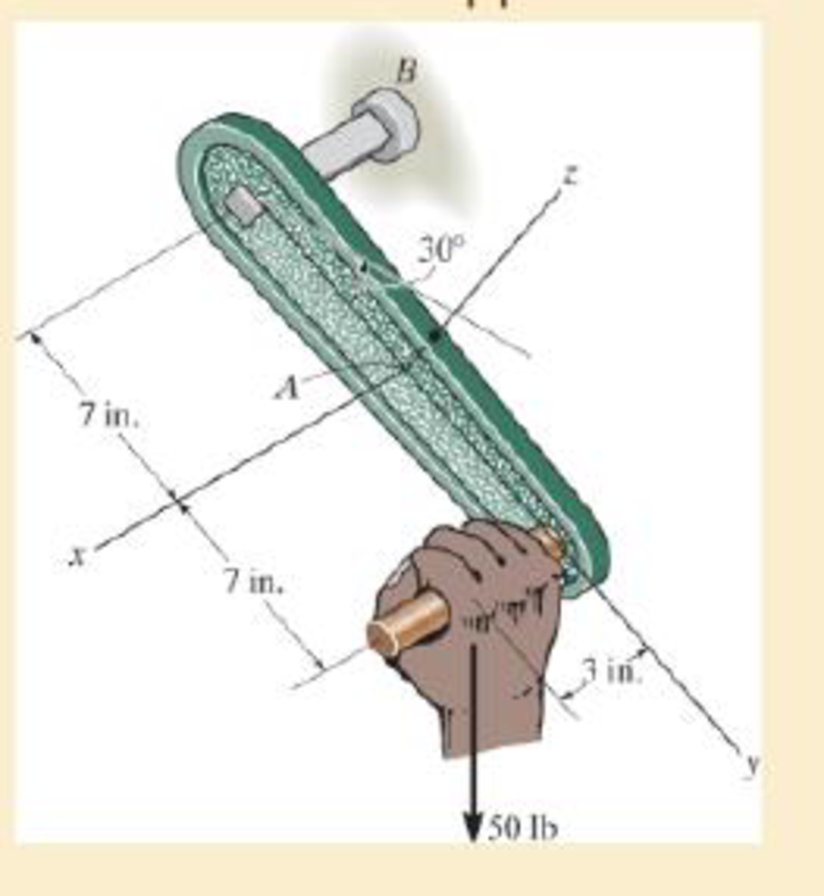
Chapter 1.2, Problem 1.19P
The hand crank that is used in a press has the dimensions shown. Determine the resultant internal loadings acting on the cross section at point A if a vertical force of 50 lb is applied to the handle as shown. Assume the crank is fixed to the shaft at B.
Expert Solution & Answer

Trending nowThis is a popular solution!

Students have asked these similar questions
Solve this problem and show all of the work
I tried to go through this problem but I don't know what I'm doing wrong can you help me?
Generate the kinematic diagram of the following mechanisms using the given symbols. Then, draw
their graphs and calculate their degrees of freedom (DoF) using Gruebler's formula.
PUNTO 2.
PUNTO 3.
!!!
Chapter 1 Solutions
MECHANICS OF MATERIALS (LOOSE)-W/ACCESS
Ch. 1.2 - In each case, explain how to find the resultant...Ch. 1.2 - Determine the resultant internal normal force,...Ch. 1.2 - Determine the resultant internal normal force,...Ch. 1.2 - Determine the resultant internal normal force,...Ch. 1.2 - Determine the resultant internal normal force,...Ch. 1.2 - Determine the resultant internal normal force,...Ch. 1.2 - Determine the resultant internal normal force,...Ch. 1.2 - The shaft is supported by a smooth thrust bearing...Ch. 1.2 - Determine the resultant internal normal and shear...Ch. 1.2 - Determine the resultant internal loadings acting...
Ch. 1.2 - The shaft is supported by a smooth thrust bearing...Ch. 1.2 - Determine the resultant internal loadings acting...Ch. 1.2 - Determine the resultant internal loadings on the...Ch. 1.2 - Determine the resultant internal loadings at cross...Ch. 1.2 - The beam supports the distributed load shown....Ch. 1.2 - The beam supports the distributed load shown....Ch. 1.2 - The boom DF of the jib crane and the column DE...Ch. 1.2 - Determine the resultant internal loadings acting...Ch. 1.2 - Determine the resultant internal loadings acting...Ch. 1.2 - The blade of the hacksaw is subjected to a...Ch. 1.2 - The blade of the hacksaw is subjected to a...Ch. 1.2 - The beam supports the triangular distributed load...Ch. 1.2 - The beam supports the distributed load shown....Ch. 1.2 - The shaft is supported at its ends by two bearings...Ch. 1.2 - The shaft is supported at its ends by two bearings...Ch. 1.2 - The hand crank that is used in a press has the...Ch. 1.2 - Determine the resultant internal loadings acting...Ch. 1.2 - Determine the resultant internal loadings acting...Ch. 1.2 - The metal stud punch is subjected to a force of...Ch. 1.2 - Determine the resultant internal loadings acting...Ch. 1.2 - Determine the resultant internal loadings acting...Ch. 1.2 - Determine the resultant internal loadings acting...Ch. 1.2 - Determine the resultant internal loadings acting...Ch. 1.2 - The pipe has a mass of 12 kg/m. If it is fixed to...Ch. 1.2 - If the drill bit jams when the brace is subjected...Ch. 1.2 - The curved rod AD of radius r has a weight per...Ch. 1.2 - A differential element taken from a curved bar is...Ch. 1.5 - In each case, determine the largest internal shear...Ch. 1.5 - Determine the largest internal normal force in the...Ch. 1.5 - Determine the internal normal force at section A...Ch. 1.5 - The lever is held to the fixed shaft using the pin...Ch. 1.5 - The single-V butt joint transmits the force of 5...Ch. 1.5 - The uniform beam is supported by two rods AB and...Ch. 1.5 - Determine the average normal stress on the cross...Ch. 1.5 - Determine the average normal stress on the cross...Ch. 1.5 - If the 600-kN force acts through the centroid of...Ch. 1.5 - Determine the average normal stress at points A,...Ch. 1.5 - Determine the average normal stress in rod AB if...Ch. 1.5 - The supporting wheel on a scaffold is held in...Ch. 1.5 - Determine the largest intensity w of the uniform...Ch. 1.5 - The bar has a cross-sectional area A and is...Ch. 1.5 - The small block has a thickness of 0.5 in. If the...Ch. 1.5 - If the material fails when the average normal...Ch. 1.5 - If the block is subjected to a centrally applied...Ch. 1.5 - The plate has a width of 0.5 m. If the stress...Ch. 1.5 - The board is subjected to a tensile force of 200...Ch. 1.5 - The boom has a uniform weight of 600 lb and is...Ch. 1.5 - Determine the average normal stress in each of the...Ch. 1.5 - If the average normal stress in each of the...Ch. 1.5 - Determine the maximum average shear stress in pin...Ch. 1.5 - If P=5 kN, determine the average shear stress in...Ch. 1.5 - Determine the maximum magnitude P of the loads the...Ch. 1.5 - The column is made of concrete having a density of...Ch. 1.5 - The beam is supported by two rods AB and CD that...Ch. 1.5 - The beam is supported by two rods AB and CD that...Ch. 1.5 - If P = 15 kN, determine the average shear stress...Ch. 1.5 - The railcar docklight is supported by the...Ch. 1.5 - The plastic block is subjected to an axial...Ch. 1.5 - The two steel members are joined together using a...Ch. 1.5 - The bar has a cross-sectional area of 400(106) m2....Ch. 1.5 - The bar has a cross-sectional area of 400(106) m2....Ch. 1.5 - The two members used in the construction of an...Ch. 1.5 - The 2-Mg concrete pipe has a center of mass at...Ch. 1.5 - The 2-Mg concrete pipe has a center of mass at...Ch. 1.5 - The pier is made of material having a specific...Ch. 1.5 - Rods AB and BC have diameters of 4 mm and 6 mm,...Ch. 1.5 - The uniform bar, having a cross-sectional area of...Ch. 1.5 - The bar has a cross-sectional area of 400(106) m2....Ch. 1.5 - The bar has a cross-sectional area of 400(106) m2....Ch. 1.5 - The prismatic bar has a cross-sectional area A. If...Ch. 1.5 - The prismatic bar has a cross-sectional area A. If...Ch. 1.5 - The bars of the truss each have a cross-sectional...Ch. 1.5 - The bars of the truss each have a cross-sectional...Ch. 1.5 - Determine the largest load P that can be applied...Ch. 1.5 - Determine the greatest constant angular velocity ...Ch. 1.5 - The radius of the pedestal is defined by r =...Ch. 1.7 - Rods AC and BC are used to suspend the 200-kg...Ch. 1.7 - If it is subjected to double shear, determine the...Ch. 1.7 - Determine the maximum average shear stress...Ch. 1.7 - If each of the three nails has a diameter of 4 mm...Ch. 1.7 - The strut is glued to the horizontal member at...Ch. 1.7 - Determine the maximum average shear stress...Ch. 1.7 - If the eyebolt is made of a material having a...Ch. 1.7 - If the bar assembly is made of a material having a...Ch. 1.7 - Determine the maximum force P that can be applied...Ch. 1.7 - The pin is made of a material having a failure...Ch. 1.7 - If the bolt head and the supporting bracket are...Ch. 1.7 - Six nails are used to hold the hanger at A against...Ch. 1.7 - If A and B are both made of wood and are 38 in....Ch. 1.7 - Prob. 1.70PCh. 1.7 - The connection is made using a bolt and nut and...Ch. 1.7 - The tension member is fastened together using two...Ch. 1.7 - The steel swivel bushing in the elevator control...Ch. 1.7 - The spring mechanism is used as a shock absorber...Ch. 1.7 - Determine the size of square bearing plates A and...Ch. 1.7 - Determine the maximum load P that can be applied...Ch. 1.7 - Determine the required diameter of the pins at A...Ch. 1.7 - If the allowable tensile stress for wires AB and...Ch. 1.7 - If the allowable tensile stress for wires AB and...Ch. 1.7 - The cotter is used to hold the two rods together....Ch. 1.7 - Determine the required diameter of the pins at A...Ch. 1.7 - The steel pipe is supported on the circular base...Ch. 1.7 - The boom is supported by the winch cable that has...Ch. 1.7 - The boom is supported by the winch cable that has...Ch. 1.7 - The assembly consists of three disks A, B, and C...Ch. 1.7 - The two aluminum rods support the vertical force...Ch. 1.7 - The two aluminum rods AB and AC have diameters of...Ch. 1.7 - Determine the required minimum thickness t of...Ch. 1.7 - Determine the maximum allowable load P that can be...Ch. 1.7 - The compound wooden beam is connected together by...Ch. 1.7 - The hanger is supported using the rectangular pin....Ch. 1.7 - The hanger is supported using the rectangular pin....Ch. 1.7 - The rods AB and CD are made of steel. Determine...Ch. 1.7 - The aluminum bracket A is used to support the...Ch. 1.7 - If the allowable tensile stress for the bar is...Ch. 1.7 - The bar is connected to the support using a pin...Ch. 1 - The beam AB is pin supported at A and supported by...Ch. 1 - The long bolt passes through the 30-mm-thick...Ch. 1 - Determine the required thickness of member BC to...Ch. 1 - The circular punch B exerts a force of 2 kN on the...Ch. 1 - Determine the average punching shear stress the...Ch. 1 - The 150 mm by 150 mm block of aluminum supports a...Ch. 1 - The yoke-and-rod connection is subjected to a...Ch. 1 - The cable has a specific weight (weight/volume)...
Knowledge Booster


Learn more about
Need a deep-dive on the concept behind this application? Look no further. Learn more about this topic, mechanical-engineering and related others by exploring similar questions and additional content below.Similar questions
- Create a schematic representation of the following mechanisms using the given symbols and draw their graphs. Then, calculate their degrees of freedom (DoF) using Gruebler's formula. PUNTO 6. PUNTO 7.arrow_forwardhow the kinematic diagram of the following mechanisms would be represented using the given symbols? PUNTO 0. PUNTO 1. °arrow_forwardCreate a schematic representation of the following mechanisms using the given symbols and draw their graphs. Then, calculate their degrees of freedom (DOF) using Gruebler's formula. PUNTO 4. PUNTO 5. (0) Groundarrow_forward
- Draw the graph of ALL the mechanisms and calculate their DoF using Gruebler's formula. PUNTO 0. PUNTO 1.arrow_forwardAn adjustable support. Construction designed to carry vertical load and is adjusted by moving the blue attachment vertically. The link is articulated at both ends (free to rotate) and can therefore only transmit power axially. Analytically calculate the force to which the link is subjected? Calculate analytically rated voltage in the middle of the link.? F=20kN Alpha 30 deg Rel 225 Mpans:5arrow_forwardA swivel crane where the load is moved axially along the beam through the wagon to which the hook is attached. Round bar with a diameter of ∅30 mm. The support beam is articulated at both ends (free to rotate) and can therefore only transmit force axially. Calculate reaction force in the x-direction at point A? Calculate analytical reaction force in the y-direction of point A? Calculate nominal stress in the middle of the support beam?Lengt 5 mAlfa 25 degX=1.5mIPE300-steelmass:1000 kgarrow_forward
- got wrong answers help pleasearrow_forwardA crate weighs 530 lb and is hung by three ropes attached to a steel ring at A such that the top surface is parallel to the xy plane. Point A is located at a height of h = 42 in above the top of the crate directly over the geometric center of the top surface. Use the dimensions given in the table below to determine the tension in each of the three ropes. 2013 Michael Swanbom cc00 BY NC SA ↑ Z C b B У a D Values for dimensions on the figure are given in the following table. Note the figure may not be to scale. Variable Value a 30 in b 43 in 4.5 in The tension in rope AB is 383 x lb The tension in rope AC is 156 x lb The tension in rope AD is 156 x lbarrow_forwardA block of mass m hangs from the end of bar AB that is 7.2 meters long and connected to the wall in the xz plane. The bar is supported at A by a ball joint such that it carries only a compressive force along its axis. The bar is supported at end B by cables BD and BC that connect to the xz plane at points C and D respectively with coordinates given in the figure. Cable BD is elastic and can be modeled as a linear spring with a spring constant k = 400 N/m and unstretched length of 6.34 meters. Determine the mass m, the compressive force in beam AB and the tension force in cable BC. Z C D (c, 0, d) (a, 0, b) A B y f m cc 10 BY NC SA 2016 Eric Davishahl x Values for dimensions on the figure are given in the following table. Note the figure may not be to scale. Variable Value a 8.1 m b 3.3 m с 2.7 m d 3.9 m e 2 m f 5.4 m The mass of the block is 68.8 The compressive force in bar AB is 364 × kg. × N. The tension in cable BC is 393 × N.arrow_forward
- The airplane weighs 144100 lbs and flies at constant speed and trajectory given by 0 on the figure. The plane experiences a drag force of 73620 lbs. 0 a.) If 11.3°, determine the thrust and lift forces = required to maintain this speed and trajectory. b.) Next consider the case where is unknown, but it is known that the lift force is equal to 7.8 times the quantity (Fthrust Fdrag). Compute the resulting trajectory angle and the lift force in this case. Use the same values for the weight and drag forces as you used for part a. 20. YAAY' Farag Ө Fthrust CC + BY NC SA 2013 Michael Swanbom Flift Fweight The lift force acts in the y' direction. The weight acts in the negative y direction. The thrust and drag forces act in the positive and negative x' directions respectively. Part (a) The thrust force is equal to 101,855 ☑ lbs. The lift force is equal to 141,282 ☑ lbs. Part (b) The trajectory angle 0 is equal to 7.31 ✓ deg. The lift force is equal to 143,005 ☑ lbs.arrow_forwardsimply supported beam has a concentrated moment M, applied at the left support and a concentrated force F applied at the free end of the overhang on the right. Using superposition, determine the deflection equations in regions AB and BC.arrow_forwardwhat is heat exchanger, what are formulas, and their importance, define the diagram, and give me a script on how to explain the design of heat exchanger, and how did values end up in that number. based on standards . what is dshellarrow_forward
arrow_back_ios
SEE MORE QUESTIONS
arrow_forward_ios
Recommended textbooks for you
 International Edition---engineering Mechanics: St...Mechanical EngineeringISBN:9781305501607Author:Andrew Pytel And Jaan KiusalaasPublisher:CENGAGE L
International Edition---engineering Mechanics: St...
Mechanical Engineering
ISBN:9781305501607
Author:Andrew Pytel And Jaan Kiusalaas
Publisher:CENGAGE L
Types Of loads - Engineering Mechanics | Abhishek Explained; Author: Prime Course;https://www.youtube.com/watch?v=4JVoL9wb5yM;License: Standard YouTube License, CC-BY