
MECHANICS OF MATERIALS (LOOSE)-W/ACCESS
10th Edition
ISBN: 9780134583228
Author: HIBBELER
Publisher: PEARSON
expand_more
expand_more
format_list_bulleted
Concept explainers
Videos
Textbook Question
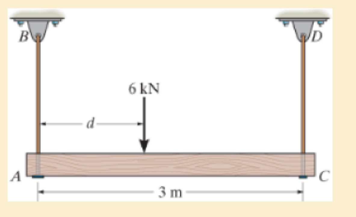
Chapter 1.5, Problem 1.47P
The beam is supported by two rods AB and CD that have cross-sectional areas of 12 mm2 and 8 mm2, respectively. Determine the position d of the 6-kN load so that the average normal stress in each rod is the same.
Expert Solution & Answer
Want to see the full answer?
Check out a sample textbook solution
Students have asked these similar questions
=
The steel curved bar shown has rectangular cross-section with a radial height h = 6 mm and thickness b = 4mm. The
radius of the centroidal axis is R = 80 mm. A force P = 10 N is applied as shown. Assume the steel modulus of
207,000 MPa and G = 79.3(103) MPa, repectively.
elasticity and shear modulus E =
Find the vertical deflection at point B. Use Castigliano's method for a curved flexural member and since R/h > 10,
neglect the effect of shear and axial load, thereby assuming that deflection is due to merely the bending moment.
Note the inner and outer radii of the curves bar are:
r = 80 + ½ (6) = 83 mm, r₁ = 80 − ½ (6) = 77 mm
2
2
Sπ/2 sin² 0 d = √π/² cos² 0 d0 =
Π
0
4
大
C
R
B
P
The steel eyebolt shown in the figure is loaded with a force F = 75 lb. The eyebolt is formed from round wire of
diameter d = 0.25 in to a radius R₁ = 0.50 in in the eye and at the shank.
Estimate the stresses at the inner and outer surfaces at section A-A.
Notice at the section A-A:
r₁ = 0.5 in, ro
= 0.75 in
rc
=
0.5 + 0.125 = 0.625 in
Ri
200
F
FA
I have the fallowing question and solution from a reeds naval arc book. Im just confused as to where this answer came from and the formulas used. Wondering if i could have this answer/ solution broken down and explained in detail.
A ship of 7000 tonne displacement has a waterplane areaof 1500 m2. In passing from sea water into river water of1005 kg/m3 there is an increase in draught of 10 cm. Find the Idensity of the sea water.
picture of the "answer" is attached
Chapter 1 Solutions
MECHANICS OF MATERIALS (LOOSE)-W/ACCESS
Ch. 1.2 - In each case, explain how to find the resultant...Ch. 1.2 - Determine the resultant internal normal force,...Ch. 1.2 - Determine the resultant internal normal force,...Ch. 1.2 - Determine the resultant internal normal force,...Ch. 1.2 - Determine the resultant internal normal force,...Ch. 1.2 - Determine the resultant internal normal force,...Ch. 1.2 - Determine the resultant internal normal force,...Ch. 1.2 - The shaft is supported by a smooth thrust bearing...Ch. 1.2 - Determine the resultant internal normal and shear...Ch. 1.2 - Determine the resultant internal loadings acting...
Ch. 1.2 - The shaft is supported by a smooth thrust bearing...Ch. 1.2 - Determine the resultant internal loadings acting...Ch. 1.2 - Determine the resultant internal loadings on the...Ch. 1.2 - Determine the resultant internal loadings at cross...Ch. 1.2 - The beam supports the distributed load shown....Ch. 1.2 - The beam supports the distributed load shown....Ch. 1.2 - The boom DF of the jib crane and the column DE...Ch. 1.2 - Determine the resultant internal loadings acting...Ch. 1.2 - Determine the resultant internal loadings acting...Ch. 1.2 - The blade of the hacksaw is subjected to a...Ch. 1.2 - The blade of the hacksaw is subjected to a...Ch. 1.2 - The beam supports the triangular distributed load...Ch. 1.2 - The beam supports the distributed load shown....Ch. 1.2 - The shaft is supported at its ends by two bearings...Ch. 1.2 - The shaft is supported at its ends by two bearings...Ch. 1.2 - The hand crank that is used in a press has the...Ch. 1.2 - Determine the resultant internal loadings acting...Ch. 1.2 - Determine the resultant internal loadings acting...Ch. 1.2 - The metal stud punch is subjected to a force of...Ch. 1.2 - Determine the resultant internal loadings acting...Ch. 1.2 - Determine the resultant internal loadings acting...Ch. 1.2 - Determine the resultant internal loadings acting...Ch. 1.2 - Determine the resultant internal loadings acting...Ch. 1.2 - The pipe has a mass of 12 kg/m. If it is fixed to...Ch. 1.2 - If the drill bit jams when the brace is subjected...Ch. 1.2 - The curved rod AD of radius r has a weight per...Ch. 1.2 - A differential element taken from a curved bar is...Ch. 1.5 - In each case, determine the largest internal shear...Ch. 1.5 - Determine the largest internal normal force in the...Ch. 1.5 - Determine the internal normal force at section A...Ch. 1.5 - The lever is held to the fixed shaft using the pin...Ch. 1.5 - The single-V butt joint transmits the force of 5...Ch. 1.5 - The uniform beam is supported by two rods AB and...Ch. 1.5 - Determine the average normal stress on the cross...Ch. 1.5 - Determine the average normal stress on the cross...Ch. 1.5 - If the 600-kN force acts through the centroid of...Ch. 1.5 - Determine the average normal stress at points A,...Ch. 1.5 - Determine the average normal stress in rod AB if...Ch. 1.5 - The supporting wheel on a scaffold is held in...Ch. 1.5 - Determine the largest intensity w of the uniform...Ch. 1.5 - The bar has a cross-sectional area A and is...Ch. 1.5 - The small block has a thickness of 0.5 in. If the...Ch. 1.5 - If the material fails when the average normal...Ch. 1.5 - If the block is subjected to a centrally applied...Ch. 1.5 - The plate has a width of 0.5 m. If the stress...Ch. 1.5 - The board is subjected to a tensile force of 200...Ch. 1.5 - The boom has a uniform weight of 600 lb and is...Ch. 1.5 - Determine the average normal stress in each of the...Ch. 1.5 - If the average normal stress in each of the...Ch. 1.5 - Determine the maximum average shear stress in pin...Ch. 1.5 - If P=5 kN, determine the average shear stress in...Ch. 1.5 - Determine the maximum magnitude P of the loads the...Ch. 1.5 - The column is made of concrete having a density of...Ch. 1.5 - The beam is supported by two rods AB and CD that...Ch. 1.5 - The beam is supported by two rods AB and CD that...Ch. 1.5 - If P = 15 kN, determine the average shear stress...Ch. 1.5 - The railcar docklight is supported by the...Ch. 1.5 - The plastic block is subjected to an axial...Ch. 1.5 - The two steel members are joined together using a...Ch. 1.5 - The bar has a cross-sectional area of 400(106) m2....Ch. 1.5 - The bar has a cross-sectional area of 400(106) m2....Ch. 1.5 - The two members used in the construction of an...Ch. 1.5 - The 2-Mg concrete pipe has a center of mass at...Ch. 1.5 - The 2-Mg concrete pipe has a center of mass at...Ch. 1.5 - The pier is made of material having a specific...Ch. 1.5 - Rods AB and BC have diameters of 4 mm and 6 mm,...Ch. 1.5 - The uniform bar, having a cross-sectional area of...Ch. 1.5 - The bar has a cross-sectional area of 400(106) m2....Ch. 1.5 - The bar has a cross-sectional area of 400(106) m2....Ch. 1.5 - The prismatic bar has a cross-sectional area A. If...Ch. 1.5 - The prismatic bar has a cross-sectional area A. If...Ch. 1.5 - The bars of the truss each have a cross-sectional...Ch. 1.5 - The bars of the truss each have a cross-sectional...Ch. 1.5 - Determine the largest load P that can be applied...Ch. 1.5 - Determine the greatest constant angular velocity ...Ch. 1.5 - The radius of the pedestal is defined by r =...Ch. 1.7 - Rods AC and BC are used to suspend the 200-kg...Ch. 1.7 - If it is subjected to double shear, determine the...Ch. 1.7 - Determine the maximum average shear stress...Ch. 1.7 - If each of the three nails has a diameter of 4 mm...Ch. 1.7 - The strut is glued to the horizontal member at...Ch. 1.7 - Determine the maximum average shear stress...Ch. 1.7 - If the eyebolt is made of a material having a...Ch. 1.7 - If the bar assembly is made of a material having a...Ch. 1.7 - Determine the maximum force P that can be applied...Ch. 1.7 - The pin is made of a material having a failure...Ch. 1.7 - If the bolt head and the supporting bracket are...Ch. 1.7 - Six nails are used to hold the hanger at A against...Ch. 1.7 - If A and B are both made of wood and are 38 in....Ch. 1.7 - Prob. 1.70PCh. 1.7 - The connection is made using a bolt and nut and...Ch. 1.7 - The tension member is fastened together using two...Ch. 1.7 - The steel swivel bushing in the elevator control...Ch. 1.7 - The spring mechanism is used as a shock absorber...Ch. 1.7 - Determine the size of square bearing plates A and...Ch. 1.7 - Determine the maximum load P that can be applied...Ch. 1.7 - Determine the required diameter of the pins at A...Ch. 1.7 - If the allowable tensile stress for wires AB and...Ch. 1.7 - If the allowable tensile stress for wires AB and...Ch. 1.7 - The cotter is used to hold the two rods together....Ch. 1.7 - Determine the required diameter of the pins at A...Ch. 1.7 - The steel pipe is supported on the circular base...Ch. 1.7 - The boom is supported by the winch cable that has...Ch. 1.7 - The boom is supported by the winch cable that has...Ch. 1.7 - The assembly consists of three disks A, B, and C...Ch. 1.7 - The two aluminum rods support the vertical force...Ch. 1.7 - The two aluminum rods AB and AC have diameters of...Ch. 1.7 - Determine the required minimum thickness t of...Ch. 1.7 - Determine the maximum allowable load P that can be...Ch. 1.7 - The compound wooden beam is connected together by...Ch. 1.7 - The hanger is supported using the rectangular pin....Ch. 1.7 - The hanger is supported using the rectangular pin....Ch. 1.7 - The rods AB and CD are made of steel. Determine...Ch. 1.7 - The aluminum bracket A is used to support the...Ch. 1.7 - If the allowable tensile stress for the bar is...Ch. 1.7 - The bar is connected to the support using a pin...Ch. 1 - The beam AB is pin supported at A and supported by...Ch. 1 - The long bolt passes through the 30-mm-thick...Ch. 1 - Determine the required thickness of member BC to...Ch. 1 - The circular punch B exerts a force of 2 kN on the...Ch. 1 - Determine the average punching shear stress the...Ch. 1 - The 150 mm by 150 mm block of aluminum supports a...Ch. 1 - The yoke-and-rod connection is subjected to a...Ch. 1 - The cable has a specific weight (weight/volume)...
Knowledge Booster


Learn more about
Need a deep-dive on the concept behind this application? Look no further. Learn more about this topic, mechanical-engineering and related others by exploring similar questions and additional content below.Similar questions
- Problem A2 long steel tube has a rectangular cross-section with outer dimensions of 20 x 20 mm and a uniform wall thickness of 2. The tube is twisted along its length with torque, T. The tube material is 1045 CD steel with shear yield strength of S,, =315 MPa. Assume shear modulus, G = 79.3GPa. (a) Estimate the maximum torque that can be applied without yielding (b) Estimate the torque required to produce 5 degrees total angle of twist over the length of the tube. (c) What is the maximum torque that can be applied without yielding, if a solid rectangular shaft with dimensions of 20 x 20 is used? You may use the exact solution.arrow_forwardA simply supported beam is loaded as shown. Considering symmetry, the reactions at supports A and B are R₁ = R₂ = wa 2 Using the singularity method, determine the shear force V along the length of the beam as a function of distance x from the support A. A B Ir. 2a За W C R₁₂ x 2. Using the singularity method, determine the bending M along the length of the beam as a function of distance x, from the support A. 3. Using the singularity method, determine the beam slope and deflection along the length of the beam as a function of the distance x, from the support A. Assume the material modulus of elasticity, E and the moment of inertia of the beam cross-section, I are given.arrow_forwardA steel tube, 2 m long, has a rectangular cross-section with outer dimensions of 20 × 30 mm and a uniform wall thickness of 1 mm. The tube is twisted along its length with torque, T. The tube material is 1018 CD steel with shear yield strength of Ssy =185 MPa. Assume shear modulus, G = 79.3GPa. (a) Estimate the maximum torque that can be applied without yielding.- (b) Estimate the torque required to produce 3 degrees total angle of twist over the length of the tube. (c) What is the maximum torque that can be applied without yielding, if a solid rectangular shaft with dimensions of 20 x 30 mm is used? You may use the exact solution:arrow_forward
- |The typical cruising altitude of a commercial jet airliner is 10,700 m above sea level where the local atmospheric temperature is 219 K, and the pressure is 0.25 bar. The aircraft utilizes a cold air-standard Brayton cycle as shown with a volume flow rate of 1450 m³/s. The compressor pressure ratio is 50, and the maximum cycle temperature is 1700 K. The compressor and turbine isentropic efficiencies are 90%. Neglect kinetic and potential energy effects in this problem. Assume constant specific heats with k=1.4, Ra=0.287 kJ/kg- K, Cp=1.0045 kJ/kg-K, and cv = 0.7175 kJ/kg-K. a) Draw a T-s diagram for this cycle on the diagram provided. b) Fill in the table below with the missing information. T[K] Heat exchanger Heat exchanger State P [bar] 1 0.25 2s 2 3 4s 4 Turbine c) (5pts) Determine the inlet air density in [kg/m³] (at state 1), and the system mass flowrate in [kg/s]. d) (10pts) Determine the net power developed in [MW]. Be sure to draw each component you are analyzing, define the…arrow_forwardOn the axis provide, draw a corresponding T-s diagram for the Brayton cycle shown given the following information: iv. V. vi. Compressor 1 is reversible, but Compressor 2 and the turbine are irreversible. The pressure drops through the regenerator are combustors are negligible. The pressures at state (1) and state (10) are equal to the atmospheric pressure. T 8 Regenerator fmm mmm Qin Combustor Compressor Compressor Turbine W cycle Intercooler mm Courarrow_forwardFor parts a) through e), consider the two power cycles shown in the diagram at the right, Cycle A: 1-2-3-4-1, and Cycle B: 1-2-3-4-1. a) What type of power cycles are shown? b) Which of cycles has a higher efficiency? c) Which of the cycles has a higher work output? d) For either cycle, would increasing the maximum cycle temperature (3) increase or decrease the efficiency? Cycle A: 1-2-3-4-1 3 3 Cycle B: 1-2-3-4-1 1 e) For either cycle, would decreasing the minimum cycle temperature (1) increase or decrease the efficiency? f) On the axis provide, draw a corresponding T-s diagram for the Rankine cycle shown given the following information: i. All turbines and pumps in the system are irreversible. ii. 111. The turbine inlet conditions (states 1 and 2) are superheated, while the 2nd stage turbine outlet is a saturated mixture. The condenser outlet state (4) and the CFWH outlet state (7) are saturated liquid. 2 Steam generator Condenser www Closed feedwater heater (1-y) T Pump Trap 8 (y) Sarrow_forward
- Problem 4 A glass sphere with a 30 mm diameter is pressed against a flat carbon steel plate with a force of 5 N. Assume. For glass: E = 46.2 GPa, -0.245 and for steel E, 207 GPa, (a) Determine the radius of the contact surface. -0.292 (4 (b) Determine the maximum pressure at the contact surface. (4 (c) Calculate the principal stresses d., and a, in the glass sphere at the depth=0.037 mm. (d) Maximum shear stress in the glass sphere at the depth: 0.037 mm. (t (4 (e) Draw the Mohr circles for the stresses and show the point corresponding to the maximum shear stress. (3arrow_forwardSteam is the working fluid in the vapor power cycle with reheat shown in the figure. The mass flow rate is 0.5 kg/s, and the turbines and pump operate isentropically. The temperature at the inlet of both turbine stages (i.e. states 1 and 3) is 400 °C The condenser outlet is saturated liquid. 1. Fill in the table below with the missing information. Reheat section High- pressure turbine State P [bar] h [kJ/kg] s [kJ/kg-K] x [-] Steam generator 1 140 Condenser Pump 2 40 5 3 4 4 5 6 2.Draw a T-s diagram for this cycle on the diagram provided 3. Determine the net power output of this cycle in [kW]. Be sure to draw the component(s) you are analyzing, define the system, and apply conservation of energy in the space below. 4.Determine the total heat transferred into the system in [kW]. Be sure to draw the component you are analyzing, define the system, and apply conservation of energy in the space bel 5.Determine the cycle efficiency. Low-pressure turbinearrow_forwardCalculate the moment of F about axis AB. Express the moment as a Cartesian vector, and then state its magnitude. The radii of the curved sections are all 0.5 m. F acts on the bottom center of the hook, and the hook lies in the yz plane.arrow_forward
- Determine the moment created by the force FAB about the point E. Assume FAB = 800 lbs. Express your answer as a Cartesian vector (ME) and state the magnitude of the moment.arrow_forwardDetermine the couple moment acting on the beam. Express it as a Cartesian vector.arrow_forwardDetermine Cartesian vector expressions for reaction forces at A and B i.e. determine FA and FB.arrow_forward
arrow_back_ios
SEE MORE QUESTIONS
arrow_forward_ios
Recommended textbooks for you
 Elements Of ElectromagneticsMechanical EngineeringISBN:9780190698614Author:Sadiku, Matthew N. O.Publisher:Oxford University Press
 Mechanics of Materials (10th Edition)Mechanical EngineeringISBN:9780134319650Author:Russell C. HibbelerPublisher:PEARSON
 Thermodynamics: An Engineering ApproachMechanical EngineeringISBN:9781259822674Author:Yunus A. Cengel Dr., Michael A. BolesPublisher:McGraw-Hill Education
 Control Systems EngineeringMechanical EngineeringISBN:9781118170519Author:Norman S. NisePublisher:WILEY
 Mechanics of Materials (MindTap Course List)Mechanical EngineeringISBN:9781337093347Author:Barry J. Goodno, James M. GerePublisher:Cengage Learning
 Engineering Mechanics: StaticsMechanical EngineeringISBN:9781118807330Author:James L. Meriam, L. G. Kraige, J. N. BoltonPublisher:WILEY
Elements Of Electromagnetics
Mechanical Engineering
ISBN:9780190698614
Author:Sadiku, Matthew N. O.
Publisher:Oxford University Press
Mechanics of Materials (10th Edition)
Mechanical Engineering
ISBN:9780134319650
Author:Russell C. Hibbeler
Publisher:PEARSON
Thermodynamics: An Engineering Approach
Mechanical Engineering
ISBN:9781259822674
Author:Yunus A. Cengel Dr., Michael A. Boles
Publisher:McGraw-Hill Education
Control Systems Engineering
Mechanical Engineering
ISBN:9781118170519
Author:Norman S. Nise
Publisher:WILEY
Mechanics of Materials (MindTap Course List)
Mechanical Engineering
ISBN:9781337093347
Author:Barry J. Goodno, James M. Gere
Publisher:Cengage Learning
Engineering Mechanics: Statics
Mechanical Engineering
ISBN:9781118807330
Author:James L. Meriam, L. G. Kraige, J. N. Bolton
Publisher:WILEY
EVERYTHING on Axial Loading Normal Stress in 10 MINUTES - Mechanics of Materials; Author: Less Boring Lectures;https://www.youtube.com/watch?v=jQ-fNqZWrNg;License: Standard YouTube License, CC-BY