
Concept explainers
Videos
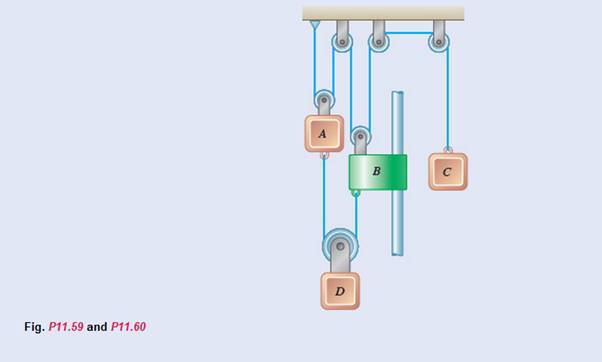
The system shown starts from rest, and the length of the upper cord is adjusted so that A, B, and C are initially at the same level. Each component moves with a constant acceleration, and after 2 s the relative change in position of block C with respect to block A is 280 mm upward. Knowing that when the relative velocity of collar B with respect to block A is 80 mm/s downward, the displacements of A and B are 160 mm downward and 320 mm downward, respectively, determine (a) the accelerations of A and B if
(a)
The acceleration of ‘A’ and ‘B’ if
Answer to Problem 11.60P
Explanation of Solution
Given information:

At
Each component moves in constant acceleration
After
The relative change in position of block ‘C’ with respect to block ‘A’ is
The velocity of collar ‘B’ with respect to ‘A’ is
The displacement of block ‘A’ is
The displacement of collar ‘B is
In a dependent motion of particles such as the pulley system shown above,
The total length of the rope is a constant
For example,
Calculation:
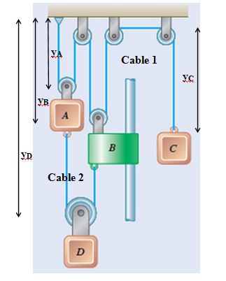
In above system, the length of each cable is constant
For cable 1,
Differentiate above equation twice,
For cable 2,
Differentiate above equation twice,
For block ‘A’
For block ‘C’
Therefore,
At,
But we know that,
Then,
For block ‘A’
For block ‘B’
Then,
But we have already found,
Therefore,
Then, for block ‘A’
Then, for collar ‘B’
Conclusion:
The acceleration of ‘A’ and ‘B’ are
(b)
The change in position of block ‘D’ when the velocity of block ‘C’ is
Answer to Problem 11.60P
Explanation of Solution
Given information:
At
Each component moves in constant acceleration
After
The relative change in position of block ‘C’ with respect to block ‘A’ is
The velocity of collar ‘B’ with respect to ‘A’ is
The displacement of block ‘A’ is
The displacement of collar ‘B is
For a uniformly accelerated motion,
In above equation,
Calculation:
According to sub part a,
We have found
Bu we know that,
Therefore,
When,
Therefore,
To find the change in distance of block ‘D’
Conclusion:
The change in distance of block ‘D’ is equal to
Want to see more full solutions like this?
Chapter 11 Solutions
Vector Mechanics For Engineers


- h = The transmission tower is subjected to the forces F₁ 3.6 KN at 50° and F2 = 3.3 kN at = 35°. Determine the forces in members BC, BP, PQ, PC, CD, DP and NP. Use positive values to indicate tension and negative values to indicate compression. 不 кажаж в *а*аж E N M d d IF, c B CENTER LINE S อ K F₂ Kbb cc 10 BY NC SA 2013 Michael Swanbom Values for dimensions on the figure are given in the following table. Note the figure may not be to scale. Variable Value a 1.7 m b 4.9 m с 3 m d 5.2 m h 8.4 m Values for dimensions on the figure are given in the following table. Note the figure may not be to scale. Variable Value a 1.7 m 4.9 m с 3 m d 5.2 m h 8.4 m The force in member BC is KN. The force in member BP is KN. The force in member PQ is KN. The force in member PC is KN. The force in member CD is KN. The force in member DP is KN. The force in member NP is KN.arrow_forwardنصاف Sheet Asteel bar of rectangular cross section with dimension Shown in fig. below. This bar is as Connected toawell. Using welded Join a long the sides als only find the weld size (h). Where: Tall = 35 MN/M² F=213.30 answer/h= 4.04 ☐ Yomm Soomm 100mmarrow_forwardFEAarrow_forward
- FEAarrow_forwardHELP?arrow_forwardTrue and False Indicate if each statement is true or false. T/F 1. Rule #1 protects the function of assembly. T/F 2. One of the fundamental dimensioning rules requires all dimensions apply in the free-state condition for rigid parts. T/F 3. The fundamental dimensioning rules that apply on a drawing must be listed in the general notes. T/F 4. Where Rule #1 applies to a drawing, it limits the form of every feature of size on the drawing. T/F 5. Rule #1 limits the variation between features of size on a part. T/F 6. The designer must specify on the drawing which features of size use Rule #1. T/F T/F T/F 7. Rule #1 applies to nonrigid parts (in the unrestrained state). 8. A GO gage is a fixed-limit gage. 9. Rule #1 requires that the form of an individual regular feature of size is controlled by its limits of sizearrow_forward
 Elements Of ElectromagneticsMechanical EngineeringISBN:9780190698614Author:Sadiku, Matthew N. O.Publisher:Oxford University Press
 Mechanics of Materials (10th Edition)Mechanical EngineeringISBN:9780134319650Author:Russell C. HibbelerPublisher:PEARSON
 Thermodynamics: An Engineering ApproachMechanical EngineeringISBN:9781259822674Author:Yunus A. Cengel Dr., Michael A. BolesPublisher:McGraw-Hill Education
 Control Systems EngineeringMechanical EngineeringISBN:9781118170519Author:Norman S. NisePublisher:WILEY
 Mechanics of Materials (MindTap Course List)Mechanical EngineeringISBN:9781337093347Author:Barry J. Goodno, James M. GerePublisher:Cengage Learning
 Engineering Mechanics: StaticsMechanical EngineeringISBN:9781118807330Author:James L. Meriam, L. G. Kraige, J. N. BoltonPublisher:WILEY