
Mechanics Of Materials, Si Edition
9th Edition
ISBN: 9789810694364
Author: Russell C Hibbeler
Publisher: Pearson Education
expand_more
expand_more
format_list_bulleted
Concept explainers
Videos
Textbook Question
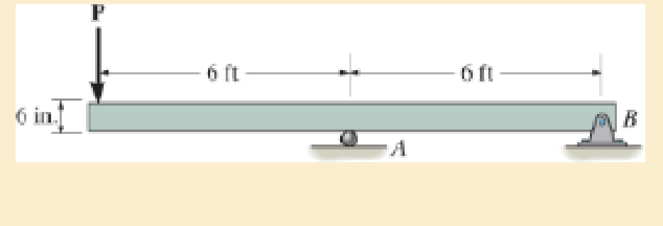
Chapter 11.2, Problem 11.3P
if P=10 kip.
Expert Solution & Answer

Trending nowThis is a popular solution!

Students have asked these similar questions
Note: please use integration for parabolic volume (Vp) of the fluid displaced due to rotation. (Make it simpe as possible to follow in the working out).
Provide a clear, step-by-step simplified handwritten solution (with no extra explanations) that is entirely produced by hand without any AI help. I require an expert-level answer, and I will assess it based on the quality and accuracy of the work, referring to the attached image for additional guidance. Make sure every detail is carefully verified for correctness before you submit. Thanks!.
Note: use centroid method please
Provide a clear, step-by-step simplified handwritten solution (with no extra explanations) that is entirely produced by hand without any AI help. I require an expert-level answer, and I will assess it based on the quality and accuracy of the work, referring to the attached image for additional guidance. Make sure every detail is carefully verified for correctness before you submit. Thanks!.
Calculate the cutting time for a 4 in length of cut, given that the feed rate is 0.030 ipr at a speed of 90 fpm.
Chapter 11 Solutions
Mechanics Of Materials, Si Edition
Ch. 11.2 - Determine the minimum dimension a to the nearest...Ch. 11.2 - of the rod to safely support the load. The rod is...Ch. 11.2 - The wood has an allowable normal stress of allow =...Ch. 11.2 - of the beam's cross section to safely support the...Ch. 11.2 - Determine the minimum dimension b to the nearest...Ch. 11.2 - The beam is made of steel having an allowable...Ch. 11.2 - Determine its dimensions if it is to be...Ch. 11.2 - Determine the minimum width of the beam to the...Ch. 11.2 - if P=10 kip.Ch. 11.2 - If the allowable bending stress is allow = 22 ksi...
Ch. 11.2 - The allowable bending stress is allow = 24 ksi and...Ch. 11.2 - The allowable bending stress is allow = 22 ksi and...Ch. 11.2 - 11–7. Draw the shear and moment diagrams for the...Ch. 11.2 - *11–8. The simply supported beam is made of timber...Ch. 11.2 - The beam has an allowable normal stress of allow =...Ch. 11.2 - The beam has an allowable normal stress of allow...Ch. 11.2 - 11–11. The timber beam is to be loaded as shown....Ch. 11.2 - If each beam is to be designed to carry 90 lb/ft...Ch. 11.2 - 11–13. Select the lightest steel wide-flange beam...Ch. 11.2 - 11–14. Select the lightest-weight steel...Ch. 11.2 - Prob. 11.15PCh. 11.2 - The beam has an allowable normal stress of allow....Ch. 11.2 - Determine the maximum cable force P that can...Ch. 11.2 - to safely support the load. The wood has an...Ch. 11.2 - and the wood has an allowable normal stress of...Ch. 11.2 - Prob. 11.20PCh. 11.2 - Prob. 11.21PCh. 11.2 - Prob. 11.22PCh. 11.2 - 11–23. The beam is constructed from three boards...Ch. 11.2 - Prob. 11.24PCh. 11.2 - Prob. 11.25PCh. 11.2 - Select the lightest-weight wide-flange beam from...Ch. 11.2 - Prob. 11.27PCh. 11.2 - * 11–28. The joist AB used in housing construction...Ch. 11.2 - If the maximum bending stress is not to exceed...Ch. 11.2 - 11–30. The simply supported beam supports a load...Ch. 11.4 - Determine the variation in the width was a...Ch. 11.4 - Prob. 11.32PCh. 11.4 - Prob. 11.33PCh. 11.4 - The beam is made from a plate that has a constant...Ch. 11.4 - Determine the variation in the depth d of a...Ch. 11.4 - Determine the variation of the radius r of the...Ch. 11.4 - Prob. 11.37PCh. 11.4 - Determine the variation in the width b as a...Ch. 11.4 - The tubular shaft has an inner diameter of 15 mm....Ch. 11.4 - Prob. 11.40PCh. 11.4 - Prob. 11.41PCh. 11.4 - Prob. 11.42PCh. 11.4 - Prob. 11.43PCh. 11.4 - Prob. 11.44PCh. 11.4 - Prob. 11.45PCh. 11.4 - Prob. 11.46PCh. 11 - The cantilevered beam has a circular cross...Ch. 11 - Select the lightest-weight wide-flange overhanging...Ch. 11 - Prob. 11.49RPCh. 11 - Determine the shaft's diameter to the nearest...Ch. 11 - Select the lightest-weight wide-flange beam from...Ch. 11 - The simply supported joist is used in the...Ch. 11 - The simply supported joist is used in the...Ch. 11 - by 4-in. pieces of wood braced as shown. If the...
Additional Engineering Textbook Solutions
Find more solutions based on key concepts
A nozzle at A discharges water with an initial velocity of 36 ft/s at an angle with the horizontal. Determine ...
Vector Mechanics For Engineers
Why is the study of database technology important?
Database Concepts (8th Edition)
17–1C A high-speed aircraft is cruising in still air. How does the temperature of air at the nose of the aircra...
Thermodynamics: An Engineering Approach
How are relationships between tables expressed in a relational database?
Modern Database Management
The following C++ program will not compile because the lines have been mixed up. cout Success\n; cout Success...
Starting Out with C++ from Control Structures to Objects (9th Edition)
The job of the _____ is to fetch instructions, carry out the operations commanded by the instructions, and prod...
Starting Out With Visual Basic (8th Edition)
Knowledge Booster


Learn more about
Need a deep-dive on the concept behind this application? Look no further. Learn more about this topic, mechanical-engineering and related others by exploring similar questions and additional content below.Similar questions
- for the values: M1=0.41m, M2=1.8m, M3=0.56m, please account for these in the equations. also please ensure that the final answer is the flow rate in litres per second for each part. please use bernoullis equation where needed if an empirical solutions i srequired. also The solutions should include, but not be limited to, the equations used tosolve the problems, the charts used to solve the problems, detailed working,choice of variables, the control volume considered, justification anddiscussion of results etc.If determining the friction factor, the use of both Moody chart and empiricalequations should be used to verify the validity of the valuearrow_forwardSolve this problem and show all of the workarrow_forwardSolve this problem and show all of the workarrow_forward
- Problem 2: An athlete, starting from rest, pulls handle A to the left with a constant force of P = 150 [N]. Knowing that after the handle A has been pulled 0.5 [m], its velocity is 5 [m/s] to the left, determine: a) A position constraint equation using the given coordinate system. b) An acceleration constraint equation. c) The acceleration of A using kinematics equations. d) The acceleration of B using your constraint equation. e) How much weight (magnitude) the athlete is lifting in pounds using Newton's 2nd Law. You must draw a FBD and KD of the circled assembly, assuming the pulleys are massless. Note: 1 [lbf] = 4.448 [N]. ХА Увarrow_forwardProblem 1: For each of the following images, draw a complete FBD and KD for the specified objects. Then write the equations of motion using variables for all unknowns (e.g., mass, friction coefficient, etc.), plugging in kinematic expressions and simplifying where appropriate. Assume motion in all cases, so any friction would be kinetic. M (a) Blocks A & B (Be careful with acceleration of B relative to accelerating block A) 30° (b) Block A being pulled up my motor M (use rotated rectangular coordinate system) 20° (c) Ball at C, top of swing (use path coordinates) (d) Parasailer/Person (use polar coordinates)arrow_forwardwhere M1=0.41m, M2=1.8m, M3=0.56m, please use bernoulis equation where necessary and The solutions should include, but not be limited to, the equations used tosolve the problems, the charts used to solve the problems, detailed working,choice of variables, the control volume considered, justification anddiscussion of results etc.If determining the friction factor, the use of both Moody chart and empiricalequations should be used to verify the validity of the value.arrow_forward
- Q3. The attachment shown in Fig.2 is made of 1040 HR. Design the weldment (give the pattern, electrode number, type of weld, length of weld, and leg size). All dimensions in mm 120 Fig.2 12 17 b =7.5 5 kN 60 60°arrow_forward15 mm DA 100 mm 50 mm Assuming the load applied P 80 kN. Determine the maximum stress in the bar shown assuming the diameter of the whole A is DA = 25 mm.arrow_forwarduse engineering economic tables, show full solutionarrow_forward
- Do not use chatgpt. I need quick handwritten solution.arrow_forwardSolve this problem and show all of the workarrow_forwardarch Moving to año Question 5 The head-vs-capacity curves for two centrifugal pumps A and B are shown below: Which of the following is a correct statement at a flow rate of 600 ft3/min? Assuming a pump efficiency of 80%. Head [ft] 50 45. 40 CHE 35. 30 25 20 PR 64°F Cloudy 4arrow_forward
arrow_back_ios
SEE MORE QUESTIONS
arrow_forward_ios
Recommended textbooks for you
 International Edition---engineering Mechanics: St...Mechanical EngineeringISBN:9781305501607Author:Andrew Pytel And Jaan KiusalaasPublisher:CENGAGE L
International Edition---engineering Mechanics: St...
Mechanical Engineering
ISBN:9781305501607
Author:Andrew Pytel And Jaan Kiusalaas
Publisher:CENGAGE L
Stresses Due to Fluctuating Loads Introduction - Design Against Fluctuating Loads - Machine Design 1; Author: Ekeeda;https://www.youtube.com/watch?v=3FBmQXfP_eE;License: Standard Youtube License