
Mechanics Of Materials, Si Edition
9th Edition
ISBN: 9789810694364
Author: Russell C Hibbeler
Publisher: Pearson Education
expand_more
expand_more
format_list_bulleted
Concept explainers
Videos
Textbook Question
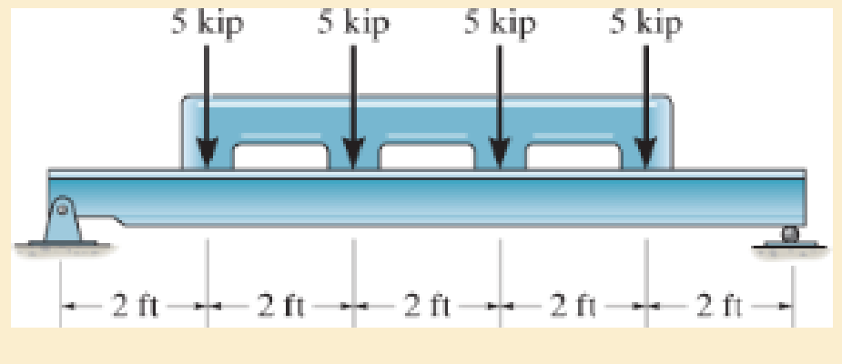
Chapter 11.2, Problem 11.5P
The allowable bending stress is σallow = 24 ksi and the allowable shear stress is τallow = 14 ksi.
Expert Solution & Answer
Want to see the full answer?
Check out a sample textbook solution
Students have asked these similar questions
Please do not use any AI tools to solve this question.
I need a fully manual, step-by-step solution with clear explanations, as if it were done by a human tutor.
No AI-generated responses, please.
Please do not use any AI tools to solve this question.
I need a fully manual, step-by-step solution with clear explanations, as if it were done by a human tutor.
No AI-generated responses, please.
Please do not use any AI tools to solve this question.
I need a fully manual, step-by-step solution with clear explanations, as if it were done by a human tutor.
No AI-generated responses, please.
Chapter 11 Solutions
Mechanics Of Materials, Si Edition
Ch. 11.2 - Determine the minimum dimension a to the nearest...Ch. 11.2 - of the rod to safely support the load. The rod is...Ch. 11.2 - The wood has an allowable normal stress of allow =...Ch. 11.2 - of the beam's cross section to safely support the...Ch. 11.2 - Determine the minimum dimension b to the nearest...Ch. 11.2 - The beam is made of steel having an allowable...Ch. 11.2 - Determine its dimensions if it is to be...Ch. 11.2 - Determine the minimum width of the beam to the...Ch. 11.2 - if P=10 kip.Ch. 11.2 - If the allowable bending stress is allow = 22 ksi...
Ch. 11.2 - The allowable bending stress is allow = 24 ksi and...Ch. 11.2 - The allowable bending stress is allow = 22 ksi and...Ch. 11.2 - 11–7. Draw the shear and moment diagrams for the...Ch. 11.2 - *11–8. The simply supported beam is made of timber...Ch. 11.2 - The beam has an allowable normal stress of allow =...Ch. 11.2 - The beam has an allowable normal stress of allow...Ch. 11.2 - 11–11. The timber beam is to be loaded as shown....Ch. 11.2 - If each beam is to be designed to carry 90 lb/ft...Ch. 11.2 - 11–13. Select the lightest steel wide-flange beam...Ch. 11.2 - 11–14. Select the lightest-weight steel...Ch. 11.2 - Prob. 11.15PCh. 11.2 - The beam has an allowable normal stress of allow....Ch. 11.2 - Determine the maximum cable force P that can...Ch. 11.2 - to safely support the load. The wood has an...Ch. 11.2 - and the wood has an allowable normal stress of...Ch. 11.2 - Prob. 11.20PCh. 11.2 - Prob. 11.21PCh. 11.2 - Prob. 11.22PCh. 11.2 - 11–23. The beam is constructed from three boards...Ch. 11.2 - Prob. 11.24PCh. 11.2 - Prob. 11.25PCh. 11.2 - Select the lightest-weight wide-flange beam from...Ch. 11.2 - Prob. 11.27PCh. 11.2 - * 11–28. The joist AB used in housing construction...Ch. 11.2 - If the maximum bending stress is not to exceed...Ch. 11.2 - 11–30. The simply supported beam supports a load...Ch. 11.4 - Determine the variation in the width was a...Ch. 11.4 - Prob. 11.32PCh. 11.4 - Prob. 11.33PCh. 11.4 - The beam is made from a plate that has a constant...Ch. 11.4 - Determine the variation in the depth d of a...Ch. 11.4 - Determine the variation of the radius r of the...Ch. 11.4 - Prob. 11.37PCh. 11.4 - Determine the variation in the width b as a...Ch. 11.4 - The tubular shaft has an inner diameter of 15 mm....Ch. 11.4 - Prob. 11.40PCh. 11.4 - Prob. 11.41PCh. 11.4 - Prob. 11.42PCh. 11.4 - Prob. 11.43PCh. 11.4 - Prob. 11.44PCh. 11.4 - Prob. 11.45PCh. 11.4 - Prob. 11.46PCh. 11 - The cantilevered beam has a circular cross...Ch. 11 - Select the lightest-weight wide-flange overhanging...Ch. 11 - Prob. 11.49RPCh. 11 - Determine the shaft's diameter to the nearest...Ch. 11 - Select the lightest-weight wide-flange beam from...Ch. 11 - The simply supported joist is used in the...Ch. 11 - The simply supported joist is used in the...Ch. 11 - by 4-in. pieces of wood braced as shown. If the...
Additional Engineering Textbook Solutions
Find more solutions based on key concepts
How is the hydrodynamic entry length defined for flow in a pipe? Is the entry length longer in laminar or turbu...
Fluid Mechanics: Fundamentals and Applications
17–1C A high-speed aircraft is cruising in still air. How does the temperature of air at the nose of the aircra...
Thermodynamics: An Engineering Approach
How are relationships between tables expressed in a relational database?
Modern Database Management
Assume a telephone signal travels through a cable at two-thirds the speed of light. How long does it take the s...
Electric Circuits. (11th Edition)
Why is the study of database technology important?
Database Concepts (8th Edition)
How does a computers main memory differ from its auxiliary memory?
Java: An Introduction to Problem Solving and Programming (8th Edition)
Knowledge Booster


Learn more about
Need a deep-dive on the concept behind this application? Look no further. Learn more about this topic, mechanical-engineering and related others by exploring similar questions and additional content below.Similar questions
- [Q2]: The cost information supplied by the cost accountant is as follows:Sales 20,00 units, $ 10 per unitCalculate the (a/ newsale guantity and (b) new selling price to earn the sameVariable cost $ 6 per unit, Fixed Cost $ 30,000, Profit $ 50,000profit ifi) Variable cost increases by $ 2 per unitil) Fixed cost increase by $ 10,000Ili) Variable cost increase by $ 1 per unit and fixed cost reduces by $ 10,000arrow_forwardcan you please help me perform Visual Inspection and Fractography of the attatched image: Preliminary examination to identify the fracture origin, suspected fatigue striation, and corrosion evidences.arrow_forwardcan you please help[ me conduct Causal Analysis (FTA) on the scenario attatched: FTA diagram which is a fault tree analysis diagram will be used to gain an overview of the entire path of failure from root cause to the top event (i.e., the swing’s detachment) and to identify interactions between misuse, material decay and inspection errors.arrow_forward
- hi can you please help me in finding the stress intensity factor using a k-calcluator for the scenario attathced in the images.arrow_forwardHi, can you please help me .Identify and justify suitable analytical techniques of the scenario below, bearing in mind the kinds of information being handled to reach a conclusion (methodology). A child swing set was discovered to have failed at the fixing at the top of the chains connecting the seat to the top of the swing set. A 12 mm threaded steel bolt, connecting the shackle to the top beam, failed at the start of the threaded region on the linkage closest to the outside side of the swing set . The linkage and bolts were made of electro galvanised mild steel . The rigid bar chain alternatives and fixings were of the same material and appeared to be fitted in accordance with guidelines. The yield strength of the steel used is 260 MPa and the UTS is 380 MPa. The bolt that failed was threaded using a standard thread with a pitch (distance between threads) of 1.75 mm and a depth of approximately 1.1 mm. The swing set in question had been assigned to ‘toddlers’ with the application of…arrow_forwardHi, can you please define and calculate the failure mode of the linkage that failed on the swing (images added) : A child swing set was discovered to have failed at the fixing at the top of the chains connecting the seat to the top of the swing set. A 12 mm threaded steel bolt, connecting the shackle to the top beam, failed at the start of the threaded region on the linkage closest to the outside side of the swing set . The linkage and bolts were made of electro galvanised mild steel . The rigid bar chain alternatives and fixings were of the same material and appeared to be fitted in accordance with guidelines. The yield strength of the steel used is 260 MPa and the UTS is 380 MPa. The bolt that failed was threaded using a standard thread with a pitch (distance between threads) of 1.75 mm and a depth of approximately 1.1 mm. The swing set in question had been assigned to ‘toddlers’ with the application of a caged-type seat. However, the location was within the play area not…arrow_forward
- Page 11-68. The rectangular plate shown is subjected to a uniaxial stress of 2000 psi. Compute the shear stress and the tensile developed on a plane forming an angle of 30° with the longitud axis of the member. (Hint: Assume a cross-sectional area of unity) 2000 psi 2000 psi hparrow_forward11-70. A shear stress (pure shear) of 5000 psi exists on an element. (a) Determine the maximum tensile and compressive stresses caused in the element due to this shear. (b) Sketch the element showing the planes on which the maximum tensile and compressive stresses act.arrow_forward11-20. An aluminum specimen of circular cross section, 0.50 in. in diameter, ruptured under a tensile load of 12,000 lb. The plane of failure was found to be at 48° with a plane perpendicular to the longitudinal axis of the specimen. (a) Compute the shear stress on the failure plane. (b) Compute the maximum tensile stress. (c) Compute the tensile stress on the failure plane. hparrow_forward
- A long flat steel bar 13 mm thick and 120 mm wide has semicircular grooves as shown and carries a tensile load of 50 kN Determine the maximum stress if plate r= 8mm r=21mm r=38mmarrow_forwardProblem 13: F₁ = A =250 N 30% Determine the moment of each of the three forces about point B. F₂ = 300 N 60° 2 m -3 m B 4 m F3=500 Narrow_forward3 kN 3 kN 1.8 kN/m 80 mm B 300 mm D an 1.5 m-1.5 m--1.5 m- PROBLEM 5.47 Using the method of Sec. 5.2, solve Prob. 5.16 PROBLEM 5.16 For the beam and loading shown, determine the maximum normal stress due to bending on a transverse section at C.arrow_forward
arrow_back_ios
SEE MORE QUESTIONS
arrow_forward_ios
Recommended textbooks for you
 Elements Of ElectromagneticsMechanical EngineeringISBN:9780190698614Author:Sadiku, Matthew N. O.Publisher:Oxford University Press
 Mechanics of Materials (10th Edition)Mechanical EngineeringISBN:9780134319650Author:Russell C. HibbelerPublisher:PEARSON
 Thermodynamics: An Engineering ApproachMechanical EngineeringISBN:9781259822674Author:Yunus A. Cengel Dr., Michael A. BolesPublisher:McGraw-Hill Education
 Control Systems EngineeringMechanical EngineeringISBN:9781118170519Author:Norman S. NisePublisher:WILEY
 Mechanics of Materials (MindTap Course List)Mechanical EngineeringISBN:9781337093347Author:Barry J. Goodno, James M. GerePublisher:Cengage Learning
 Engineering Mechanics: StaticsMechanical EngineeringISBN:9781118807330Author:James L. Meriam, L. G. Kraige, J. N. BoltonPublisher:WILEY
Elements Of Electromagnetics
Mechanical Engineering
ISBN:9780190698614
Author:Sadiku, Matthew N. O.
Publisher:Oxford University Press
Mechanics of Materials (10th Edition)
Mechanical Engineering
ISBN:9780134319650
Author:Russell C. Hibbeler
Publisher:PEARSON
Thermodynamics: An Engineering Approach
Mechanical Engineering
ISBN:9781259822674
Author:Yunus A. Cengel Dr., Michael A. Boles
Publisher:McGraw-Hill Education
Control Systems Engineering
Mechanical Engineering
ISBN:9781118170519
Author:Norman S. Nise
Publisher:WILEY
Mechanics of Materials (MindTap Course List)
Mechanical Engineering
ISBN:9781337093347
Author:Barry J. Goodno, James M. Gere
Publisher:Cengage Learning
Engineering Mechanics: Statics
Mechanical Engineering
ISBN:9781118807330
Author:James L. Meriam, L. G. Kraige, J. N. Bolton
Publisher:WILEY
Everything About COMBINED LOADING in 10 Minutes! Mechanics of Materials; Author: Less Boring Lectures;https://www.youtube.com/watch?v=N-PlI900hSg;License: Standard youtube license