
Videos
Consider a two-stage cascade refrigeration cycle with a flash chamber as shown in the figure with refrigerant-134a as the working fluid. The evaporator temperature is −10°C and the condenser pressure is 1600 kPa. The refrigerant leaves the condenser as a saturated liquid and is throttled to a flash chamber operating at 0.45 MPa. Part of the refrigerant evaporates during this flashing process, and this vapor is mixed with the refrigerant leaving the low-pressure compressor. The mixture is then compressed to the condenser pressure by the high-pressure compressor. The liquid in the flash chamber is throttled to the evaporator pressure and cools the refrigerated space as it vaporizes in the evaporator. The mass flow rate of the refrigerant through the low-pressure compressor is 0.11 kg/s. Assuming the refrigerant leaves the evaporator as a saturated vapor and the isentropic efficiency is 86 percent for both compressors, determine (a) the mass flow rate of the refrigerant through the high-pressure compressor, (b) the rate of refrigeration supplied by the system, and (c) the COP of this refrigerator. Also, determine (d) the rate of refrigeration and the COP if this refrigerator operated on a single-stage vapor-compression cycle between the same evaporating temperature and condenser pressure with the same compressor efficiency and the same flow rate as calculated in part a.
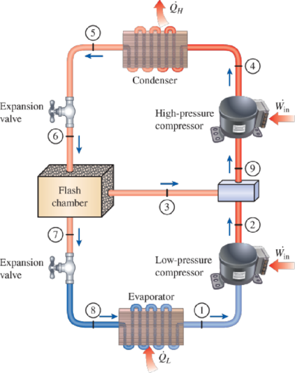
FIGURE P11–65
(a)
The mass flow rate of the refrigerant through the high-pressure compressor.
Answer to Problem 65P
The mass flow rate of the refrigerant through the high-pressure compressor is
Explanation of Solution
Show the T-s diagram as in Figure (1).
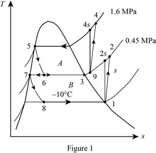
From Figure (1), write the specific enthalpy at state 6 is equal to state 5 due to throttling process.
Here, specific enthalpy at state 6 and 5 is
From Figure (1), write the specific enthalpy at state 8 is equal to state 7 due to throttling process.
Here, specific enthalpy at state 8 and 7 is
Express enthalpy at state 1.
Here, enthalpy saturation vapor at temperature of
Express entropy at state 1.
Here, entropy saturation vapor at temperature of
Express the specific enthalpy at state 2.
Here, specific enthalpy at state 2s is
Express enthalpy at state 3.
Here, enthalpy saturation vapor at pressure of
Express enthalpy at state 5.
Here, enthalpy saturation liquid at pressure of
Express enthalpy at state 7.
Here, enthalpy saturation liquid at pressure of
Express the quality at state 6.
Express the mass flow rate of the refrigerant.
Here, mass flow rate at state 7 is
Conclusion:
Refer Table A-11, “saturated refrigerant-134a-temperature table”, and write enthalpy saturation vapor at temperature of
Substitute
Refer Table A-11, “saturated refrigerant-134a-temperature table”, and write entropy saturation vapor at temperature of
Substitute
Perform the unit conversion of pressure at state 2 from
Refer Table A-13, “superheated refrigerant 134a”, and write the specific enthalpy at state 2s corresponding to pressure at state 2 of
Here, enthalpy at state 2s is
Substitute
Refer Table A-12, “saturated refrigerant-134a-pressure table”, and write the enthalpy saturation vapor at pressure of
Substitute
Refer Table A-12, “saturated refrigerant-134a-pressure table”, and write the enthalpy saturation liquid at pressure of
Substitute
Substitute
Refer Table A-12, “saturated refrigerant-134a-pressure table”, and write the enthalpy saturation liquid at pressure of
Substitute
Substitute
Substitute
Substitute
Hence, the mass flow rate of the refrigerant through the high-pressure compressor is
(b)
The rate of refrigeration supplied by the system.
Answer to Problem 65P
The rate of refrigeration supplied by the system is
Explanation of Solution
Express the mass flow rate at state 3.
Express the enthalpy at state 9.
Express the enthalpy at state 4.
Here, specific enthalpy at state 4s is
Express the rate of heat removal from the refrigerated space.
Conclusion:
Substitute
Substitute
Refer Table A-13, “superheated refrigerant 134a”, and write the specific enthalpy at state 9 corresponding to pressure at state 9 of
Here, entropy at state 9 is
Refer Table A-13, “superheated refrigerant 134a”, and write the specific enthalpy at state 4s corresponding to pressure at state 4 of
Write the formula of interpolation method of two variables.
Here, the variables denote by x and y is specific entropy at state 9 and specific enthalpy at state 4s respectively.
Show the specific enthalpy at state 4s corresponding to specific entropy as in Table (1).
|
Specific entropy at state 9 |
Specific enthalpy at state 4s |
| 0.9164 | 280.71 |
| 0.9399 | |
| 0.9536 | 293.27 |
Substitute
Thus, the specific enthalpy at state 4s is,
Substitute
Substitute
Hence, the rate of refrigeration supplied by the system is
(c)
The COP of the refrigerator.
Answer to Problem 65P
The COP of the refrigerator is
Explanation of Solution
Express the power input.
Express the coefficient of performance.
Conclusion:
Substitute
Substitute
Hence, the coefficient of performance of the refrigerator is
(d)
The rate of refrigeration and the COP of the refrigerator.
Answer to Problem 65P
The rate of refrigeration is
Explanation of Solution
Show the T-s diagram as in Figure (1).
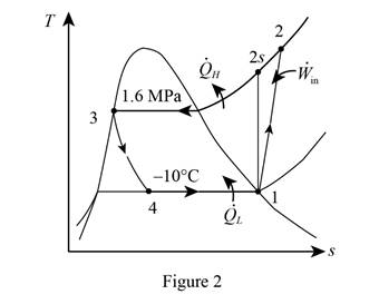
From Figure (1), write the specific enthalpy at state 4 is equal to state 3 due to throttling process.
Here, specific enthalpy at state 4 and 3 is
Express the enthalpy at state 2.
Here, specific enthalpy at state 2s is
Express enthalpy at state 3.
Here, enthalpy saturation vapor at pressure of
Express the rate of refrigeration.
Express the rate of work input.
Express the coefficient of performance.
Conclusion:
Refer Table A-13, “superheated refrigerant 134a”, and write the specific enthalpy at state 2s corresponding to pressure at state 2 of
Show the specific enthalpy at state 2s corresponding to specific entropy as in Table (2).
|
Specific entropy at state 2 |
Specific enthalpy at state 2s |
| 0.9164 | 280.71 |
| 0.9378 | |
| 0.9536 | 293.27 |
Use excels and tabulates the values from Table (2) in Equation (XV) to get,
Thus, the specific enthalpy at state 2s is,
Substitute
Refer Table A-12, “saturated refrigerant-134a-pressure table”, and write the enthalpy saturation liquid at pressure of
Substitute
Substitute
Substitute
Hence, the rate of refrigeration is
Substitute
Substitute
Hence, the coefficient of performance of the refrigerator is
Want to see more full solutions like this?
Chapter 11 Solutions
EBK THERMODYNAMICS: AN ENGINEERING APPR


- Experiment تكنولوجيا السيارات - Internal Forced convenction Heat transfer Air Flow through Rectangular Duct. objective: Study the convection heat transfer of air flow through rectangular duct. Valve Th Top Dead Centre Exhaust Valve Class CP. N; ~ RIVavg Ti K 2.11 Te To 18.8 21.3 45.8 Nath Ne Pre Calculations:. Q = m cp (Te-Ti) m: Varg Ac Acca*b Q=hexp As (Ts-Tm) 2 2.61 18.5 20.846.3 Tm = Te-Ti = 25 AS-PL = (a+b)*2*L Nu exp= Re-Vavy D heep Dh k 2ab a+b Nu Dh the- (TS-Tm) Ts. Tmy Name / Nu exp Naxe بب ارتدان العشريarrow_forwardProcedure:1- Cartesian system, 2D3D,type of support2- Free body diagram3 - Find the support reactions4- If you find a negativenumber then flip the force5- Find the internal force3D∑Fx=0∑Fy=0∑Fz=0∑Mx=0∑My=0\Sigma Mz=02D\Sigma Fx=0\Sigma Fy=0\Sigma Mz=05- Use method of sectionand cut the elementwhere you want to findarrow_forwardProcedure:1- Cartesian system, 2D3D,type of support2- Free body diagram3 - Find the support reactions4- If you find a negativenumber then flip the force5- Find the internal force3D∑Fx=0∑Fy=0∑Fz=0∑Mx=0∑My=0\Sigma Mz=02D\Sigma Fx=0\Sigma Fy=0\Sigma Mz=05- Use method of sectionand cut the elementwhere you want to findthe internal force andkeep either side of thearrow_forward
- Procedure: 1- Cartesian system, 2D3D, type of support 2- Free body diagram 3 - Find the support reactions 4- If you find a negative number then flip the force 5- Find the internal force 3D ∑Fx=0 ∑Fy=0 ∑Fz=0 ∑Mx=0 ∑My=0 ΣMz=0 2D ΣFx=0 ΣFy=0 ΣMz=0 5- Use method of section and cut the element where you want to find the internal force and keep either side of thearrow_forwardProcedure:1- Cartesian system, 2D3D,type of support2- Free body diagram3 - Find the support reactions4- If you find a negativenumber then flip the force5- Find the internal force3D∑Fx=0∑Fy=0∑Fz=0∑Mx=0∑My=0\Sigma Mz=02D\Sigma Fx=0\Sigma Fy=0\Sigma Mz=05- Use method of sectionand cut the elementwhere you want to findthe internal force andkeep either side of thearrow_forwardProcedure: 1- Cartesian system, 2(D)/(3)D, type of support 2- Free body diagram 3 - Find the support reactions 4- If you find a negative number then flip the force 5- Find the internal force 3D \sum Fx=0 \sum Fy=0 \sum Fz=0 \sum Mx=0 \sum My=0 \Sigma Mz=0 2D \Sigma Fx=0 \Sigma Fy=0 \Sigma Mz=0 5- Use method of section and cut the element where you want to find the internal force and keep either side of the sectionarrow_forward
- Procedure: 1- Cartesian system, 2(D)/(3)D, type of support 2- Free body diagram 3 - Find the support reactions 4- If you find a negative number then flip the force 5- Find the internal force 3D \sum Fx=0 \sum Fy=0 \sum Fz=0 \sum Mx=0 \sum My=0 \Sigma Mz=0 2D \Sigma Fx=0 \Sigma Fy=0 \Sigma Mz=0 5- Use method of section and cut the element where you want to find the internal force and keep either side of the sectionarrow_forwardFor each system below with transfer function G(s), plot the pole(s) on the s-plane. and indicate whether the system is: (a) "stable" (i.e., a bounded input will always result in a bounded output), (b) "marginally stable," or (c) "unstable" Sketch a rough graph of the time response to a step input. 8 a) G(s) = 5-5 8 b) G(s) = c) G(s) = = s+5 3s + 8 s² - 2s +2 3s +8 d) G(s): = s²+2s+2 3s+8 e) G(s): = s² +9 f) G(s): 8 00 == Sarrow_forwardPlease answer the following question. Include all work and plase explain. Graphs are provided below. "Consider the Mg (Magnesium) - Ni (Nickel) phase diagram shown below. This phase diagram contains two eutectic reactions and two intermediate phases (Mg2Ni and MgNi2). At a temperature of 505oC, determine what the composition of an alloy would need to be to contain a mass fraction of 0.20 Mg and 0.80 Mg2Ni."arrow_forward
- The triangular plate, having a 90∘∘ angle at AA, supports the load PP = 370 lblb as shown in (Figure 1).arrow_forwardDesign a 4-bar linkage to carry the body in Figure 1 through the two positions P1 and P2 at the angles shown in the figure. Use analytical synthesis with the free choice values z = 1.075, q= 210°, ß2 = −27° for left side and s = 1.24, y= 74°, ½ = − 40° for right side. φ 1.236 P2 147.5° 210° 2.138 P1 Figure 1 Xarrow_forwardDesign a 4-bar linkage to carry the body in Figure 1 through the two positions P1 and P2 at the angles shown in the figure. Use analytical synthesis with the free choice values z = 1.075, q= 210°, B₂ = −27° for left side and s = 1.24, y= 74°, ½ = − 40° for right side. 1.236 P2 147.5° 210° P1 Figure 1 2.138 Xarrow_forward
 Refrigeration and Air Conditioning Technology (Mi...Mechanical EngineeringISBN:9781305578296Author:John Tomczyk, Eugene Silberstein, Bill Whitman, Bill JohnsonPublisher:Cengage Learning