
Videos
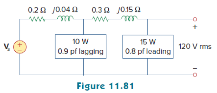
For the circuit in Fig. 11.81, find Vs.
Find the voltage
Answer to Problem 62P
The voltage
Explanation of Solution
Given data:
Refer to Figure 11.81 in the textbook.
The voltage
For load A,
The real power
The power factor
For load B,
The real power
The power factor
Formula used:
Write the expression to find the complex power.
Here,
Write the expression to find the power factor
Here,
Write the expression to find the real power.
Write the expression to find the reactive power.
Write the expression to find the output voltage.
Calculation:
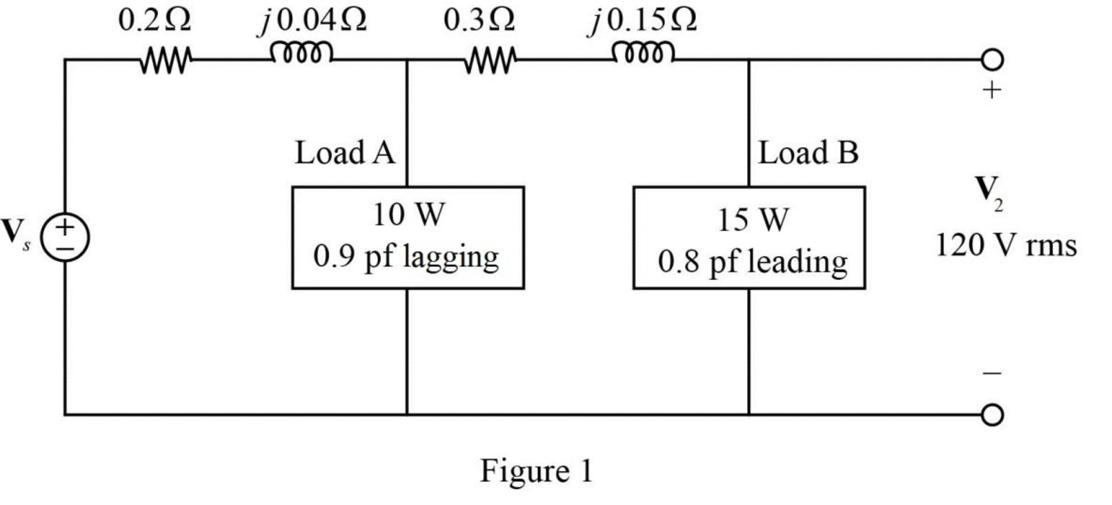
The given Figure 11.81 is redrawn as shown in Figure 1.
For load A:
Substitute
Substitute
Rearrange the equation as follows,
Substitute
Substitute
For load B:
Substitute
Substitute
Rearrange the equation as follows,
Substitute
Substitute
As the power factor is leading, the load is capacitive. Therefore, the equation becomes,
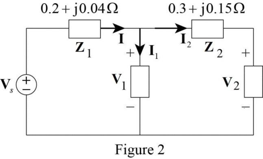
The modified Figure is shown in Figure 2.
Substitute
The voltage
Substitute
Substitute
Convert the equation from polar to rectangular form.
The current
Substitute
The voltage supplied by the source is,
Substitute
Convert the equation from rectangular to polar form.
Conclusion:
Thus, the voltage
Want to see more full solutions like this?
Chapter 11 Solutions
EE 98: Fundamentals of Electrical Circuits - With Connect Access


- Q1: Write a VHDL code to implement the finite state machine described in the state diagram shown below. Clk D 0 CIK Q D 0 Cik Q =arrow_forwardQ1: Consider the finite state machine logic implementation in Fig. shown below: Construct the state diagram. Repeat the circuit design using j-k flip flop. r" Clk Y D' Y, Clk Q D Clk 10 0 22 3'2arrow_forwardQ: Write a VHDL code to implement the finite state machine described in the state diagram shown below. T 2 Clk Q Clk T₂ 0 la Clk T3 Q Cik 0arrow_forward
- Do you happen to know what is the complete circuit?arrow_forwardb) Draw the magnitude and phase bode plot c) Given Cdb=0.02pF, how will the frequency response change, draw the resulting magnitude and phase bode plotplz help me to solve part b and c.arrow_forwardMedium 1 is a lossless dielectric (ε₁, μ₁ = μo, σ₁ = 0) Medium 2 is a perfect electric conductor (PEC) ( 2 = 0, μ2 = μo, σ₂ = ∞) [ Moσ = 0] [ε0 μ₁ σ₂ = ∞ ] (J=σE is finite, E = 0) E(z) Exe² +Пe₁²] 1. For the case εr] = λι = = E2(z)-0 - 1 (vacuum), E₁x 1 V/m and a frequency f = 500 MHz determine: n₁ = 12= 2. Determine: r = T= 3. Using this I show that the total electric field E₁0(z) in region 1 can be written as: E(z) = -2jE, sin(2лz/λ)✰ 4. The magnitude E10(z) will show an interference pattern. The SWR (standing wave ratio) is the Emax/Emin ratio of the magnitude of the total electric field in region 1. What is the SWR? E (z) = 2|E|sin(2лz/2₁)| E" (z) SWR A Imax E(z) Imin 1+r 1-|| tot 5. Roughly SKETCH the magnitude of E10(z) and E20(z) on the graph below. E₁tot(z) tot E20(z) -0.40 -0.30 -0.ło z=0 +0.1b +0.20arrow_forward
- would anyone be able to tell me the amount of wire needed for this electrical plan in this house? and if possible would anyone be able to tell me the amount of any other materials needed (wire sizes, box sizes/styles)arrow_forwardPlease show all stepsarrow_forwardA plane wave propagating in the +z direction in medium 1 is normally incident to medium 2 located at the z=0 plane as below. Both mediums are general, characterized by ( ε i, Mi, Ơi ). tot = [ ει μη σ] [ε, μη σε ] Ex Ex tot E₁₂ (z) = Ee Ex z=0 From conservation of energy: P₁AV'(z=0) + Piav'(z=0) = P2av²(z=0). Using the above show for lossless media that: ( 1 - ||²) = (1/M2 )|T|² .arrow_forward
- A plane wave propagating in the +z direction in medium 1 is normally incident to medium 2 located at the z=0 plane as below. Both mediums are general, characterized by ( ε i, Hi, σ¡ ). [ ει μη σ] Ex [ ει μη ση ] Ex tot E₁₂ (z) = E'₁e¹² -122 E(z) = Ee+ E₁₁₁² E₁x z=0 1. Specify the electric field reflection coefficient г and transmission coefficient T: E ΓΔ E E TA EL 2. Show that T=1+г. Can the transmitted electric field amplitude in region 2 be LARGER than the incident electric field amplitude? 3. Determine expressions for P₁AV'(z), PIAV'(z) and P2AV'(z) (note the sign for the reflected power direction should be (-z).arrow_forward2) In the ideal transformer circuit shown below find Vo and the complex power supplied by the source. 292 www b 1:4 16 Ω ww + + 240/0° V rms -12492arrow_forward3) In the ideal autotransformer circuit shown below find 11, 12 and lo. Find the average power delivered to the load. (hint: write KVL for both sides) 20/30° V(+ 2-1602 200 turns V₂ 10 + j40 Ω 80 turns V₁arrow_forward
 Delmar's Standard Textbook Of ElectricityElectrical EngineeringISBN:9781337900348Author:Stephen L. HermanPublisher:Cengage Learning