
EE 98: Fundamentals of Electrical Circuits - With Connect Access
6th Edition
ISBN: 9781259981807
Author: Alexander
Publisher: MCG
expand_more
expand_more
format_list_bulleted
Concept explainers
Videos
Textbook Question
Chapter 11, Problem 11P
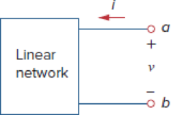
For the network in Fig. 11.43, assume that the port impedance is
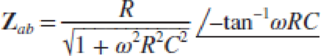
Find the average power consumed by the network when R = 10 kΩ, C = 200 nF, and i = 33 sin(377t + 22°) mA.
Figure 11.43
Expert Solution & Answer
Want to see the full answer?
Check out a sample textbook solution
Students have asked these similar questions
Assignment #2
A 110-V, three-phase, Y-connected, 8 pole, 48-slot, 6000-rpm,
double-layer wound, synchronous generator has 12 turns per coil.
If one side of the coil is in slot 1, the other side is in slot 6. There
are 4 parallel paths. When the generator delivers the rated load at
a line voltage of 110 V, the voltage regulation is 5%. What is the
flux per pole?
Draw two consecutive phasegroups of one of the phase windings
and connect them (a) in series and (b) in parallel showing the
Start (S) and Finish (F) of both connections. (A separate drawing
for each connection)
3-4 Transmissiva Live of 120km has
R= 0.2
~2/15
X= 0.8 -2/km
Y = 15H/6 5/km
The line is supplies a load of 45 kV, SOMW, 0.8 lead p.f
find sending voltage,
Sending Current
p.f. Sanding
Voltage Regulation
⑨Voltage
5
Ⓒ charching coming!
изу
usy π cct
ले
A (medium) single phase transmission line 100 km long has the following
constants :
Resistance/km = 0.25 Q;
Susceptance/km = 14 × 10° siemen ;
Reactance/km = 0.8
Receiving end line voltage = 66,000 V
Assuming that the total capacitance of the line is localised at the receiving end alone, determine
(i) the sending end current (ii) the sending end voltage (iii) regulation and (iv) supply power factor.
The line is delivering 15,000 kW at 0.8 power factor Lead Draw the phasor diagram to illustrate
your calculations.
Chapter 11 Solutions
EE 98: Fundamentals of Electrical Circuits - With Connect Access
Ch. 11.2 - Calculate the instantaneous power and average...Ch. 11.2 - A current A flows through an impedance Find the...Ch. 11.2 - In the circuit of Fig. 11.4, calculate the average...Ch. 11.2 - Calculate the average power absorbed by each of...Ch. 11.3 - For the circuit shown in Fig. 11.10, find the load...Ch. 11.3 - In Fig. 11.12, the resistor RL is adjusted until...Ch. 11.4 - Find the rms value of the current waveform of Fig....Ch. 11.4 - Find the rms value of the full-wave rectified sine...Ch. 11.5 - Prob. 9PPCh. 11.5 - Prob. 10PP
Ch. 11.6 - For a load, Determine: (a) the complex and...Ch. 11.6 - A sinusoidal source supplies 100 kVAR reactive...Ch. 11.7 - In the circuit in Fig. 11.25, the 60- resistor...Ch. 11.7 - Two loads connected in parallel are respectively 3...Ch. 11.8 - Find the value of parallel capacitance needed to...Ch. 11.9 - For the circuit in Fig. 11.33, find the wattmeter...Ch. 11.9 - The monthly reading of a paper mills meter is as...Ch. 11.9 - An 500-kW induction furnace at 0.88 power factor...Ch. 11 - The average power absorbed by an inductor is zero,...Ch. 11 - The Thevenin impedance of a network seen from the...Ch. 11 - The amplitude of the voltage available in the...Ch. 11 - If the load impedance is 20 j20, the power factor...Ch. 11 - A quantity that contains all the power information...Ch. 11 - Reactive power is measured in: (a) watts (b) VA...Ch. 11 - In the power triangle shown in Fig. 11.34(a), the...Ch. 11 - For the power triangle in Fig. 11.34(b), the...Ch. 11 - A source is connected to three loads Z1, Z2, and...Ch. 11 - The instrument for measuring average power is the:...Ch. 11 - If v(t) = 160 cos 50t V and i(t) = 33 sin (50t ...Ch. 11 - Given the circuit in Fig. 11.35, find the average...Ch. 11 - A load consists of a 60- resistor in parallel with...Ch. 11 - Using Fig. 11.36, design a problem to help other...Ch. 11 - ssuming that vs = 8 cos(2t 40) V in the circuit...Ch. 11 - For the circuit in Fig. 11.38, is = 6 cos 103t A....Ch. 11 - Given the circuit of Fig. 11.39, find the average...Ch. 11 - In the circuit of Fig. 11.40, determine the...Ch. 11 - For the op amp circuit in Fig. 11.41, Find the...Ch. 11 - In the op amp circuit in Fig. 11.42, find the...Ch. 11 - For the network in Fig. 11.43, assume that the...Ch. 11 - For the circuit shown in Fig. 11.44, determine the...Ch. 11 - The Thevenin impedance of a source is ZTh = 120 +...Ch. 11 - Using Fig. 11.45, design a problem to help other...Ch. 11 - In the circuit of Fig. 11.46, find the value of ZL...Ch. 11 - For the circuit in Fig. 11.47, find the value of...Ch. 11 - Calculate the value of ZL in the circuit of Fig....Ch. 11 - Find the value of ZL in the circuit of Fig. 11.49...Ch. 11 - The variable resistor R in the circuit of Fig....Ch. 11 - The load resistance RL in Fig. 11.51 is adjusted...Ch. 11 - Assuming that the load impedance is to be purely...Ch. 11 - Find the rms value of the offset sine wave shown...Ch. 11 - Using Fig. 11.54, design a problem to help other...Ch. 11 - Determine the rms value of the waveform in Fig....Ch. 11 - Find the rms value of the signal shown in Fig....Ch. 11 - Find the effective value of the voltage waveform...Ch. 11 - Calculate the rms value of the current waveform of...Ch. 11 - Find the rms value of the voltage waveform of Fig,...Ch. 11 - Calculate the effective value of the current...Ch. 11 - Compute the rms value of the waveform depicted in...Ch. 11 - Find the rms value of the signal shown in Fig....Ch. 11 - Obtain the rms value of the current waveform shown...Ch. 11 - Determine the rms value for the waveform in Fig....Ch. 11 - Find the effective value f(t) defined in Fig....Ch. 11 - One cycle of a periodic voltage waveform is...Ch. 11 - Calculate the rms value for each of the following...Ch. 11 - Design a problem to help other students better...Ch. 11 - For the power system in Fig. 11.67, find: (a) the...Ch. 11 - An ac motor with impedance ZL = 2 + j 1.2 is...Ch. 11 - Design a problem to help other students better...Ch. 11 - Obtain the power factor for each of the circuits...Ch. 11 - A 110-V rms, 60-Hz source is applied to a load...Ch. 11 - Design a problem to help other students understand...Ch. 11 - Find the complex power delivered by vs to the...Ch. 11 - The voltage across a load and the current through...Ch. 11 - For the following voltage and current phasors,...Ch. 11 - For each of the following cases, find the complex...Ch. 11 - Determine the complex power for the following...Ch. 11 - Find the complex power for the following cases:...Ch. 11 - Obtain the overall impedance for the following...Ch. 11 - For the entire circuit in Fig. 11.70, calculate:...Ch. 11 - In the circuit of Fig. 11.71, device A receives 2...Ch. 11 - In the circuit of the Fig. 11.72, load A receives...Ch. 11 - For the network in Fig. 11.73, find the complex...Ch. 11 - Using Fig. 11.74, design a problem to help other...Ch. 11 - Obtain the complex power delivered by the source...Ch. 11 - For the circuit in Fig. 11.76, find the average,...Ch. 11 - Obtain the complex power delivered to the 10-k...Ch. 11 - Calculate the reactive power in the inductor and...Ch. 11 - For the circuit in Fig. 11.79, find Vo and the...Ch. 11 - Given the circuit in Fig. 11.80, find Io and the...Ch. 11 - For the circuit in Fig. 11.81, find Vs.Ch. 11 - Find Io in the circuit of Fig. 11.82. Figure 11.82Ch. 11 - Determine Is in the circuit of Fig. 11.83, if the...Ch. 11 - In the op amp circuit of Fig. 11.84, vs = 4 cos...Ch. 11 - Obtain the average power absorbed by the 10-...Ch. 11 - For the op amp circuit in Fig. 11.86, calculate:...Ch. 11 - Compute the complex power supplied by the current...Ch. 11 - Refer to the circuit shown in Fig. 11.88. (a) What...Ch. 11 - Design a problem to help other students better...Ch. 11 - Three loads are connected in parallel to a rms...Ch. 11 - Two loads connected in parallel draw a total of...Ch. 11 - A 240-V rms 60-Hz supply serves a load that is 10...Ch. 11 - A 120-V rms 60-Hz source supplies two loads...Ch. 11 - Consider the power system shown in Fig. 11.90....Ch. 11 - Obtain the wattmeter reading of the circuit in...Ch. 11 - What is the reading of the wattmeter in the...Ch. 11 - Find the wattmeter reading of the circuit shown in...Ch. 11 - Determine the wattmeter reading of the circuit in...Ch. 11 - The circuit of Fig. 11.95 portrays a wattmeter...Ch. 11 - Design a problem to help other students better...Ch. 11 - A 240-V rms 60-Hz source supplies a parallel...Ch. 11 - Oscilloscope measurements indicate that the peak...Ch. 11 - A consumer has an annual consumption of 1200 MWh...Ch. 11 - A regular household system of a single-phase...Ch. 11 - A transmitter delivers maximum power to an antenna...Ch. 11 - In a TV transmitter, a series circuit has an...Ch. 11 - A certain electronic circuit is connected to a...Ch. 11 - An industrial heater has a nameplate that reads:...Ch. 11 - A 2000-kW turbine-generator of 0.85 power factor...Ch. 11 - The nameplate of an electric motor has the...Ch. 11 - As shown in Fig. 11.97, a 550-V feeder line...Ch. 11 - A factory has the following four major loads: A...Ch. 11 - A 1-MVA substation operates at full load at 0.7...Ch. 11 - Prob. 95CPCh. 11 - A power amplifier has an output impedance of 40 +...Ch. 11 - A power transmission system is modeled as shown in...
Knowledge Booster


Learn more about
Need a deep-dive on the concept behind this application? Look no further. Learn more about this topic, electrical-engineering and related others by exploring similar questions and additional content below.Similar questions
- 1. An electromagnetic device is shown below. The coil in the left side is connected to a steady AC power source. The left coil generates a changing magnetic flux, which is = 1.5cos(120πt +л/6) T. Calculate the voltage vs generated across the right coil given the number of turns of the right coil is 5 (You only need to calculate the magnitude). Vparrow_forwardFor the closed loop system shown in figure, determine the following:arrow_forwardWhat is the open loop transfer function and feedback for thia system? Determine the type of the open loop system. Find the poles s1 and s2 of the open loop system. If the input is a step function R(s)=1/s, find the step response c(t) of the open loop.arrow_forward
- not use ai please don'tarrow_forward2. A DC generator is shown below. This DC generator is driven by a prime mover and rotating in counterclockwise direction. The armature is connected with a load resistor. (i) Using cross (x) or dot (*) to indicate the current direction of each conductor in the armature. (ii) If we want to reverse the polarity of the generated armature voltage, what can we do to? rotation S load Narrow_forward6. The figures below show the equivalent circuit of a separately excited DC generator and the approximate relationship between the flux of main field and exciting current. The field current I can be regulated by the variable resistor Ry, and the battery voltage supplying power to the exciter is 12V. The armature resistance Ro is 20, and the load is 182. For the DC generator, we aim to keep the voltage across the load (RL) constant in different speed range conditions. In the beginning, the flux is 0.12 Wb, the DC generator speed is 1000 rpm, and the generated voltage E。 is 100 V. Calculate: (1) The current flowing through the load. (2) When the speed of generator changes to 1500 rpm, how should we adjust the exciting current Ix to ensure Ę is still 100 V. (Hint: E₁ = Zno/60) (3) When the speed of generator changes to 500 rpm, how should we adjust the exciting current Ix to ensure Eo is still 100 V. (Hint: Eo = Zno/60) Rf ww (Wb) 0.17 0.15 12 V 1x F ele 1 1 2 ell Eo Ro ww 9 w RL Ix (A)arrow_forward
- 7. For a shunt excited motor, the maximum allowable current is twice of the full-load current. The full-load current is 10 A. The equivalent circuit of this motor is also shown below. The rheostat can change the resistance by moving the slider (contact). The counter electromotive force (CEMF) for this motor is 100 V at 1000 rpm. The power supply E, is 200 V. In this case: (1) Calculate the minimum resistor value R at 0 rpm ensuing the motor is running within the safe range, and calculate the power consumed by the rheostat R. (2) Calculate the minimum effective resistor value R at 100 rpm ensuing the motor is running within the safe range, and calculate the power consumed by the rheostat R and the delivered mechanical power. (3) Calculate the minimum resistor value R at 500 rpm ensuing the motor is running within the safe range, and calculate the power consumed by the rheostat R the delivered mechanical power. shunt field R armature rheostat Es + Eoarrow_forward4. For a general DC generator, we aim to achieve constant output voltage at different rotating speeds. (1) List two factors influencing the output voltage for a given DC generator. (2) How does the change of the load (assuming the load is the current flowing though the resistor) will impact on the generated voltage for (a) separately excited DC generator, (b) Shunt DC generator, and (c) cumulative compound DC generator?arrow_forward3. A DC motor is shown below. The armature is supplied by an external battery, and the current flowing direction of each conduction is depicted in the figure. (i) Draw the Lorentz force direction applied on each conductor in the armature. (ii) In which direction will the motor spin? What can we do to reverse the spinning direction? S Narrow_forward
- 5. conditions. For a general DC motor, we aim to control the speed of the motor at different loading (1) List two factors influencing the motor speed for a given DC motor. (2) List three ways to stop a motor and comment on each method?arrow_forwardSolve by Pen and Paper not using chatgptarrow_forwardf. The figure below shows two stage RC coupled amplifier. If the input resistance Rin of each stage is 1kN. (B = 100). Determine its overall voltage gain. (5 marks) +15V ΣΚΩ kn 10kΩ 10ΚΩ output 35 ΚΩ 2ΚΩ 5kЛ 2ΚΩarrow_forward
arrow_back_ios
SEE MORE QUESTIONS
arrow_forward_ios
Recommended textbooks for you
 Introductory Circuit Analysis (13th Edition)Electrical EngineeringISBN:9780133923605Author:Robert L. BoylestadPublisher:PEARSON
 Delmar's Standard Textbook Of ElectricityElectrical EngineeringISBN:9781337900348Author:Stephen L. HermanPublisher:Cengage Learning
 Programmable Logic ControllersElectrical EngineeringISBN:9780073373843Author:Frank D. PetruzellaPublisher:McGraw-Hill Education
 Fundamentals of Electric CircuitsElectrical EngineeringISBN:9780078028229Author:Charles K Alexander, Matthew SadikuPublisher:McGraw-Hill Education
 Electric Circuits. (11th Edition)Electrical EngineeringISBN:9780134746968Author:James W. Nilsson, Susan RiedelPublisher:PEARSON
 Engineering ElectromagneticsElectrical EngineeringISBN:9780078028151Author:Hayt, William H. (william Hart), Jr, BUCK, John A.Publisher:Mcgraw-hill Education,
Introductory Circuit Analysis (13th Edition)
Electrical Engineering
ISBN:9780133923605
Author:Robert L. Boylestad
Publisher:PEARSON
Delmar's Standard Textbook Of Electricity
Electrical Engineering
ISBN:9781337900348
Author:Stephen L. Herman
Publisher:Cengage Learning
Programmable Logic Controllers
Electrical Engineering
ISBN:9780073373843
Author:Frank D. Petruzella
Publisher:McGraw-Hill Education
Fundamentals of Electric Circuits
Electrical Engineering
ISBN:9780078028229
Author:Charles K Alexander, Matthew Sadiku
Publisher:McGraw-Hill Education
Electric Circuits. (11th Edition)
Electrical Engineering
ISBN:9780134746968
Author:James W. Nilsson, Susan Riedel
Publisher:PEARSON
Engineering Electromagnetics
Electrical Engineering
ISBN:9780078028151
Author:Hayt, William H. (william Hart), Jr, BUCK, John A.
Publisher:Mcgraw-hill Education,
How Electric Motors Work - 3 phase AC induction motors ac motor; Author: The Engineering Mindset;https://www.youtube.com/watch?v=59HBoIXzX_c;License: Standard Youtube License