
Introductory Circuit Analysis (13th Edition)
13th Edition
ISBN: 9780133923605
Author: Robert L. Boylestad
Publisher: PEARSON
expand_more
expand_more
format_list_bulleted
Videos
Textbook Question
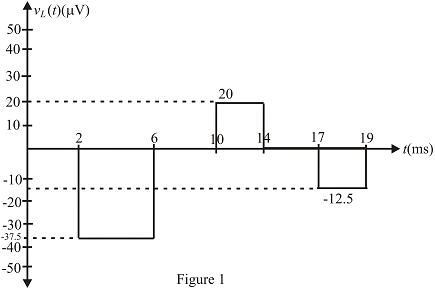
Chapter 11, Problem 35P
Find the waveform for the voltage induced across a 5mH coil if the current through the coil is as shown in Fig. 11.100.
Expert Solution & Answer
Want to see the full answer?
Check out a sample textbook solution
Students have asked these similar questions
Consider the following logic functions:
f = x₁x2x3 + x2X4 +X1X2X4 +X2X3X+X1X2X3
8 = (x2+x3 + x4)(x1+x2 + x4)(x2+x3+X4)(x1+x2+x3)(x1+x2+x4)
Prove or disprove that f = g
No AI, Use pencil and paper
1. For the circuit shown, let Is = 10, R₁-45, R2-5, R3-5, and R4-45, to find:
(choose the closest value in volts) (V)
{NOTE: On Multiple Choice Questions, like this problem, you have only one attempt }
• Vab
50
(V)
-25
225
R₁
a
R2
RA
b
R3
Vab
Chapter 11 Solutions
Introductory Circuit Analysis (13th Edition)
Ch. 11 - For the electromagnet in Fig. 11.75: a. Find the...Ch. 11 - For the inductor in Fig. 11.76, find the...Ch. 11 - a. Repeat Problem 2 with a ferromagnetic core with...Ch. 11 - For the inductor in Fig. 11.77, find the...Ch. 11 - An air-core inductor has a total inductance of 4.7...Ch. 11 - What are the inductance and the range of expected...Ch. 11 - If the flux linking a coil of 50 turns changes at...Ch. 11 - Determine the rate of change of flux linking a...Ch. 11 - How many turns does a coil have if 42 mV are...Ch. 11 - Find the voltage induced across a coil of 22 mH if...
Ch. 11 - For the circuit of Fig. 11.78 composed of standard...Ch. 11 - For the circuit in Fig. 11.79 composed of standard...Ch. 11 - For the network of Fig. 11.80. a. Write the...Ch. 11 - Give a supply of 18 V, use standard values to...Ch. 11 - For the circuit in Fig. 11.82: a. Write the...Ch. 11 - In this problem, the effect of reversing the...Ch. 11 - For the network of Fig. 11.84: a. Find the...Ch. 11 - Prob. 18PCh. 11 - Prob. 19PCh. 11 - Prob. 20PCh. 11 - For the network in Fig. 11.88: a. Determine the...Ch. 11 - For the network in Fig. 11.89: a. Write the...Ch. 11 - Prob. 23PCh. 11 - For Fig. 11.91: a. Determine the mathematical...Ch. 11 - For Fig. 11.92: a. Determine the mathematical...Ch. 11 - For the network in Fig. 11.93, the switch is...Ch. 11 - The switch in Fig. 11.94 has been open for a long...Ch. 11 - Prob. 28PCh. 11 - The switch for the network in Fig. 11.96 has been...Ch. 11 - The switch in Fig. 11.97 has been closed for a...Ch. 11 - Given iL=100mA(1e-t/20ms) a. Determine iLatt=1ms....Ch. 11 - a. If the measured current for an inductor during...Ch. 11 - The network in Fig. 11.98 employs a DMM with an...Ch. 11 - Find the waveform for the voltage induced across a...Ch. 11 - Find the waveform for the voltage induced across a...Ch. 11 - Prob. 36PCh. 11 - Find the total inductance of the circuit of Fig....Ch. 11 - Find the total inductance for the network of Fig....Ch. 11 - Reduce the network in Fig. 11.104 to the fewest...Ch. 11 - Reduce the network in Fig. 11.105 to the fewest...Ch. 11 - Reduce the network of Fig. 11.106 to the fewest...Ch. 11 - For the network in Fig. 11.107: a. Write the...Ch. 11 - For the network in Fig. 11.108: a. Write the...Ch. 11 - For the network in Fig. 11.109. a. Find the...Ch. 11 - Find the steady-state currents I1 and I2 for the...Ch. 11 - Find the steady-state currents and voltages for...Ch. 11 - Find the steady-state currents and voltages for...Ch. 11 - Find the indicated steady-state currents and...Ch. 11 - Prob. 49PCh. 11 - Using PSpice or Multisim, verify the results of...Ch. 11 - Using the PSpice or Multisim, find the solution to...Ch. 11 - Using PSpice or Multisim, find the solution to...Ch. 11 - Using PSpice or Multisim, verify the results of...
Knowledge Booster


Learn more about
Need a deep-dive on the concept behind this application? Look no further. Learn more about this topic, electrical-engineering and related others by exploring similar questions and additional content below.Similar questions
- power systemsarrow_forwardFind G(s) = Vs(s) / Ve(s) for this circuit belowarrow_forwardCalculate the magnitude of the current in the coils e1, e2 of the magnetic circuit, if: ɸa = 3,00 x 10⁻³ Wb, φb = 0,80 x 10⁻³ Wb, ɸc = 2,20 x 10⁻³ Wb L AB = 0,10 m, L AFEB = L ACDB = 0,40 m AAB = 5,0 cm2 A AFEB = A ACDB = 20 cm2 Material characteristics H (At/m) 240 350 530 1300 5000 9000 B (T) 0,7 0,9 1,1 1,3 1,5 1,6arrow_forward
- Power systemsarrow_forwardExplain the advantages and disadvantages of using silicon (Si) anode versus graphitic anode (C6) and write charging reactions for these anodes. Explain the effect of increasing state of charge window (SOC) of lithium battery and how SOC-window impact energy density and cycle life of the battery.arrow_forwardPower Systemarrow_forward
- 3. Consider the circuit, in which R₁ = 10 KQ2, R2 = 5 KQ, R3 = 1 KQ, and RE = 8 KQ. The supply voltages are +Vcc = 10 V and -VEE = -5 V. Other parameters are ẞF = 100, VBE(On) = 0.7 V, and VCE(Sat) 0.2 V. Rc value will be specified later. (a) (3 points) Draw the dc equivalent circuit of the circuit. VI +Vcc Rc R2 RI R₁ RE -VEE υο R3 (b) Find the Thevenin equivalent voltage source VEQ and input resistance REQ of the DC equivalent circuit. Show your work. +Vcc Rc UC VEQ www REQ VE VEQ = REQ = ΚΩ RE VEEarrow_forward5. Consider the ac equivalent circuit of an amplifier, where RE = 1 KS2, gm = 0.05 S, and Υπ= 2Κ Ω. (a) Redraw the ac equivalent circuit using the hybrid-pi small signal model for BJTS. Include ro in the model. R₁ ww Vi RB ww + RL Vo RE (b) Find the terminal resistance RIB using the circuit obtained in (a). Ignore ro. Show your work. (Don't use formula for RiB.)arrow_forward4. Consider the circuit. Use the symbol || to indicate the parallel of resistors in the following questions. (a) Express the input resistance Rin in terms of the terminal resistance and other necessary resistor values. (In other words, RiB, Ric, and RIE are given.) C₁ R₁ R₂ +Vcc Rc C3 R3 C2 ی RE -VEE (b) Express the output resistance Rout in terms of the terminal resistance and other necessary resistor values. (In other words, RiB, Ric and RiE are given.) (c) Express the voltage gain A₁ = ∞ in terms of terminal voltage gain Avt, the terminal Vi resistance, and other necessary resistor values. (Avt, RiB, Ric and R₁E are given.) +51arrow_forward
arrow_back_ios
SEE MORE QUESTIONS
arrow_forward_ios
Recommended textbooks for you
 Delmar's Standard Textbook Of ElectricityElectrical EngineeringISBN:9781337900348Author:Stephen L. HermanPublisher:Cengage Learning
Delmar's Standard Textbook Of Electricity
Electrical Engineering
ISBN:9781337900348
Author:Stephen L. Herman
Publisher:Cengage Learning
How do Universal Motors work ?; Author: Lesics;https://www.youtube.com/watch?v=0PDRJKz-mqE;License: Standard Youtube License