
Introductory Circuit Analysis (13th Edition)
13th Edition
ISBN: 9780133923605
Author: Robert L. Boylestad
Publisher: PEARSON
expand_more
expand_more
format_list_bulleted
Videos
Textbook Question
Chapter 11, Problem 15P
For the circuit in Fig. 11.82:
a. Write the mathematical expressions for the current iL and the voltage vL following the closing of the switch. Note the magnitude and the direction of the initial current.
b. Sketch the waveform of iL and vL for the entire period from initial value to steady-state level.
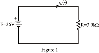
Fig. 11.82
Expert Solution & Answer

Trending nowThis is a popular solution!

Students have asked these similar questions
. 30-dB, right-circularly polarized antenna in a radio link radiates 5-W of power
t 2 GHz. The input impedance of this antenna is 75 ohms, and it is attached
ɔ a 50-ohm transmission line.
The receiving antenna has an impedance mismatch at its terminals, -
which leads to a VSWR of 2. The receiving antenna is about 95% efficient and
has a field pattern near the beam maximum given by E, = (2âx + jây) F, (0, 0).
The distance between the two antennas is 4,000 km, and the receiving antenna
Directivity is 100. Determine the Minimum power
Delivered to receiving antenna.
1
Open plc - ladder logic To control traffic, we have red lights to stop cars and green lights to initiate entry/exit.
If a car is in the lane, then the red lights turn ON. If no cars are in the lane, then the
green lights turn ON. Upon turning ON the main switch button, the main switch indicator
should turn ON and the system should start with green lights ON and red lights OFF?
3-4)
3.4-2 Signals g₁(t) = 104П(104) and g2(t) = 8(t) are applied at the inputs of the ideal low-pass
filters H₁(f)=(f/20,000) and H2(f) = П(f/10,000) (Fig. P3.4-2). The outputs y₁ (t) and
y2(t) of these filters are multiplied to obtain the signal y(t) = y1 (1)y2(t).
(a) Sketch G1(f) and G2(f).
(b) Sketch H₁(f) and H₂(f).
(c) Sketch Y₁ (f) and Y2(f).
(d) Find the bandwidths of y₁ (t), y2(t), and y(t).
8₁ (1)
H₁(f)
y, (t)
y(t) = y₁ (1) y2 (1)
82(1)
½⁄2 (1)
H₂(f)
Chapter 11 Solutions
Introductory Circuit Analysis (13th Edition)
Ch. 11 - For the electromagnet in Fig. 11.75: a. Find the...Ch. 11 - For the inductor in Fig. 11.76, find the...Ch. 11 - a. Repeat Problem 2 with a ferromagnetic core with...Ch. 11 - For the inductor in Fig. 11.77, find the...Ch. 11 - An air-core inductor has a total inductance of 4.7...Ch. 11 - What are the inductance and the range of expected...Ch. 11 - If the flux linking a coil of 50 turns changes at...Ch. 11 - Determine the rate of change of flux linking a...Ch. 11 - How many turns does a coil have if 42 mV are...Ch. 11 - Find the voltage induced across a coil of 22 mH if...
Ch. 11 - For the circuit of Fig. 11.78 composed of standard...Ch. 11 - For the circuit in Fig. 11.79 composed of standard...Ch. 11 - For the network of Fig. 11.80. a. Write the...Ch. 11 - Give a supply of 18 V, use standard values to...Ch. 11 - For the circuit in Fig. 11.82: a. Write the...Ch. 11 - In this problem, the effect of reversing the...Ch. 11 - For the network of Fig. 11.84: a. Find the...Ch. 11 - Prob. 18PCh. 11 - Prob. 19PCh. 11 - Prob. 20PCh. 11 - For the network in Fig. 11.88: a. Determine the...Ch. 11 - For the network in Fig. 11.89: a. Write the...Ch. 11 - Prob. 23PCh. 11 - For Fig. 11.91: a. Determine the mathematical...Ch. 11 - For Fig. 11.92: a. Determine the mathematical...Ch. 11 - For the network in Fig. 11.93, the switch is...Ch. 11 - The switch in Fig. 11.94 has been open for a long...Ch. 11 - Prob. 28PCh. 11 - The switch for the network in Fig. 11.96 has been...Ch. 11 - The switch in Fig. 11.97 has been closed for a...Ch. 11 - Given iL=100mA(1e-t/20ms) a. Determine iLatt=1ms....Ch. 11 - a. If the measured current for an inductor during...Ch. 11 - The network in Fig. 11.98 employs a DMM with an...Ch. 11 - Find the waveform for the voltage induced across a...Ch. 11 - Find the waveform for the voltage induced across a...Ch. 11 - Prob. 36PCh. 11 - Find the total inductance of the circuit of Fig....Ch. 11 - Find the total inductance for the network of Fig....Ch. 11 - Reduce the network in Fig. 11.104 to the fewest...Ch. 11 - Reduce the network in Fig. 11.105 to the fewest...Ch. 11 - Reduce the network of Fig. 11.106 to the fewest...Ch. 11 - For the network in Fig. 11.107: a. Write the...Ch. 11 - For the network in Fig. 11.108: a. Write the...Ch. 11 - For the network in Fig. 11.109. a. Find the...Ch. 11 - Find the steady-state currents I1 and I2 for the...Ch. 11 - Find the steady-state currents and voltages for...Ch. 11 - Find the steady-state currents and voltages for...Ch. 11 - Find the indicated steady-state currents and...Ch. 11 - Prob. 49PCh. 11 - Using PSpice or Multisim, verify the results of...Ch. 11 - Using the PSpice or Multisim, find the solution to...Ch. 11 - Using PSpice or Multisim, find the solution to...Ch. 11 - Using PSpice or Multisim, verify the results of...
Knowledge Booster


Learn more about
Need a deep-dive on the concept behind this application? Look no further. Learn more about this topic, electrical-engineering and related others by exploring similar questions and additional content below.Similar questions
- solve the differential equation y'' -2y'-3y=x³e^5x cos(3x) Don't use AI,I need it handwrittenarrow_forward3-3) Similar to Lathi & Ding prob. 3.3-7. The signals in the figure below are modulated signals with carrier cos(5t). Find the Fourier transforms of these signals using the appropriate properties of the Fourier transform and text Table 3.1. The sketch the magnitude and phase spectra for figure parts (a) and (b). Hint: these functions can be expressed in the form g(t) cos(2лfot) (a) 1 1 2π www. σπ (b) (c) όπarrow_forward3-1) Similar to Lathi & Ding prob. 3.1-1. Use direct integration to find the Fourier transforms of the signals shown below. a) g₁(t) = II(t − 2) + 2 exp (−3|t|) b) g(t) = d(t+2)+3e¯u (t − 2)arrow_forward
- Fundamentals of Energy Systems HW 4 Q6arrow_forwardConstruct a battery pack to deliver 360V and 450-mile range for a vehicle that consumes 200 Wh/mile, from prismatic cells with 25Ah and 3.6 V. Physical dimensions of the cell are 0.5 cm thickness, 20 cm width and 40 cm length. a) Report configuration of the battery pack. 10-points b) Resistance of each cell is 0.05 Ohm, calculate the total internal resistance of the battery pack. 10-points c) Calculate the voltage drop during discharge when the battery is discharged at 100A. 10-points d) Calculate the amount of anode and cathode to build a prismatic cell with 25Ah capacity. Assume the cell chemistry as: Si anode and [Li(Ni1/3Co1/3Mn1/3)O2] cathode. Atomic weight of elements: Li=7, Si = 28, Ni=58, Co=59, Mn=55, O=16, 10-points e) Calculate the theoretical specific energy (Wh/kg) and practical energy density (Wh/liter) of the battery pack. 10-points f) Calculate the thickness on anode and cathode coating assuming each electrode has 30%…arrow_forwardI need help with this problem and an explanation of the solution for the image described below. (Introduction to Signals and Systems)arrow_forward
arrow_back_ios
SEE MORE QUESTIONS
arrow_forward_ios
Recommended textbooks for you
 Power System Analysis and Design (MindTap Course ...Electrical EngineeringISBN:9781305632134Author:J. Duncan Glover, Thomas Overbye, Mulukutla S. SarmaPublisher:Cengage Learning
Power System Analysis and Design (MindTap Course ...
Electrical Engineering
ISBN:9781305632134
Author:J. Duncan Glover, Thomas Overbye, Mulukutla S. Sarma
Publisher:Cengage Learning
How do Universal Motors work ?; Author: Lesics;https://www.youtube.com/watch?v=0PDRJKz-mqE;License: Standard Youtube License