
Introductory Circuit Analysis (13th Edition)
13th Edition
ISBN: 9780133923605
Author: Robert L. Boylestad
Publisher: PEARSON
expand_more
expand_more
format_list_bulleted
Videos
Textbook Question
Chapter 11, Problem 30P
The switch in Fig. 11.97 has been closed for a long time. It is then opened at
a. Write the mathematical expression for the current iL and the voltage vL after the switch is opened.
b. Sketch the waveform of iL and vL from initial value to the steady-state leve.
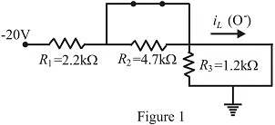
Fig. 11.97
Expert Solution & Answer
Want to see the full answer?
Check out a sample textbook solution
Students have asked these similar questions
5 A
Q4) A thin ring of radius 5 cm is placed on plane z = 1 cm so that its center is at
(0,0,1 cm). If the ring carries 50 mA along a^, find H at (0,0,a).
Q6) Find the current density J for the magnetic field intensity vectors:
(a) H = x²ya, + y²zay - 2xza,
(b) H = p²zap + p³a + 3pz²az
sin
cos
(c) H =
a,
2
+2
Q2) Line x = 0, y=0,0
Chapter 11 Solutions
Introductory Circuit Analysis (13th Edition)
Ch. 11 - For the electromagnet in Fig. 11.75: a. Find the...Ch. 11 - For the inductor in Fig. 11.76, find the...Ch. 11 - a. Repeat Problem 2 with a ferromagnetic core with...Ch. 11 - For the inductor in Fig. 11.77, find the...Ch. 11 - An air-core inductor has a total inductance of 4.7...Ch. 11 - What are the inductance and the range of expected...Ch. 11 - If the flux linking a coil of 50 turns changes at...Ch. 11 - Determine the rate of change of flux linking a...Ch. 11 - How many turns does a coil have if 42 mV are...Ch. 11 - Find the voltage induced across a coil of 22 mH if...
Ch. 11 - For the circuit of Fig. 11.78 composed of standard...Ch. 11 - For the circuit in Fig. 11.79 composed of standard...Ch. 11 - For the network of Fig. 11.80. a. Write the...Ch. 11 - Give a supply of 18 V, use standard values to...Ch. 11 - For the circuit in Fig. 11.82: a. Write the...Ch. 11 - In this problem, the effect of reversing the...Ch. 11 - For the network of Fig. 11.84: a. Find the...Ch. 11 - Prob. 18PCh. 11 - Prob. 19PCh. 11 - Prob. 20PCh. 11 - For the network in Fig. 11.88: a. Determine the...Ch. 11 - For the network in Fig. 11.89: a. Write the...Ch. 11 - Prob. 23PCh. 11 - For Fig. 11.91: a. Determine the mathematical...Ch. 11 - For Fig. 11.92: a. Determine the mathematical...Ch. 11 - For the network in Fig. 11.93, the switch is...Ch. 11 - The switch in Fig. 11.94 has been open for a long...Ch. 11 - Prob. 28PCh. 11 - The switch for the network in Fig. 11.96 has been...Ch. 11 - The switch in Fig. 11.97 has been closed for a...Ch. 11 - Given iL=100mA(1e-t/20ms) a. Determine iLatt=1ms....Ch. 11 - a. If the measured current for an inductor during...Ch. 11 - The network in Fig. 11.98 employs a DMM with an...Ch. 11 - Find the waveform for the voltage induced across a...Ch. 11 - Find the waveform for the voltage induced across a...Ch. 11 - Prob. 36PCh. 11 - Find the total inductance of the circuit of Fig....Ch. 11 - Find the total inductance for the network of Fig....Ch. 11 - Reduce the network in Fig. 11.104 to the fewest...Ch. 11 - Reduce the network in Fig. 11.105 to the fewest...Ch. 11 - Reduce the network of Fig. 11.106 to the fewest...Ch. 11 - For the network in Fig. 11.107: a. Write the...Ch. 11 - For the network in Fig. 11.108: a. Write the...Ch. 11 - For the network in Fig. 11.109. a. Find the...Ch. 11 - Find the steady-state currents I1 and I2 for the...Ch. 11 - Find the steady-state currents and voltages for...Ch. 11 - Find the steady-state currents and voltages for...Ch. 11 - Find the indicated steady-state currents and...Ch. 11 - Prob. 49PCh. 11 - Using PSpice or Multisim, verify the results of...Ch. 11 - Using the PSpice or Multisim, find the solution to...Ch. 11 - Using PSpice or Multisim, find the solution to...Ch. 11 - Using PSpice or Multisim, verify the results of...
Knowledge Booster


Learn more about
Need a deep-dive on the concept behind this application? Look no further. Learn more about this topic, electrical-engineering and related others by exploring similar questions and additional content below.Similar questions
- Q4) Given the magnetic vector potential: A = y²z ax-(x + 1)z² az A/m Find(a) the magnetic flux density; (b)the magnetic flux through a square loop described by 0≤x≤1, 0 ≤ y ≤1, z=2.arrow_forwardQ5) Consider the following arbitrary fields. Find out which of them can possibly represent electrostatic or magnetostatic field in free space. (a) A = y cos axa, + (y + ea, (b) B 20 р (c) C = r² sin 0 aarrow_forwardEx. 12 plane y=l carries current k = 50āz Find at- roro) ره α)- ⑥(1.5-3). Hw marrow_forward
- Please, my dear teacher, solve the question on a piece of paper, not with artificial intelligence, then show the final matrix in the solution. Subject the Control Systemarrow_forwardAn Aluminum wire 2250Ft long cannot have a resistance greater than 0.2 ohms. What is the minimum size of wire that may be used?arrow_forwardCalculate the resistance for Aluminum wire, 8 AWG with a length of 1000 FT*arrow_forward
- Introduction The circuit of Fig. 1 is required to be modeled using a state - space representation, where 2 states will be used, based on the number of the energy - storing elements of the circuit, the capacitor and the inductor. u(t) + ΙΩ www 13 F 5 Ω it (t) www vc(t) 1 H Figure 1: LCR circuit The input signal to the circuit is the voltage u(t) in Volts and the output signal is the voltage across the capacitor, vc(t). Questions 1. Choice of system states: Choose appropriate signals for the 2 states of the system. x₁(t) = i₁(t) x₂ (t) =arrow_forward5. State transition matrix: (t), which is defined as, Calculate analytically the state transition matrix (t) = et = L¯¹{(sI – A)¯¹} Show that the answer is the following, 1 e-4t cos(√2t) - e-4 sin(√2 t) 1 e -4t √2 (t) = et -3 1 -4t sin (√2 t) e COS -4t cos (√2t) + - e sin(√2 t) 2-4t sin(√2 t)| Calculate the following: (SI - A)-1= Use the completion - in - the-square technique (CASE 3) to calculate the inverse Laplace: L¯¹{(SI - A)¯¹} =arrow_forwardA single-core cable working on 66 kV has a conductor diameter of 2 cm and the sheath of inside diameter is 10 cm. If two metallic intersheaths of diameters 5 cm, 8 cm respectively are used for grading the cable.. If the maximum electric stress is the same for each layers. 1- Find the voltage of each metallic intersheaths. 2- Find the thickness of each layers.arrow_forward
arrow_back_ios
SEE MORE QUESTIONS
arrow_forward_ios
Recommended textbooks for you
 Introductory Circuit Analysis (13th Edition)Electrical EngineeringISBN:9780133923605Author:Robert L. BoylestadPublisher:PEARSON
 Delmar's Standard Textbook Of ElectricityElectrical EngineeringISBN:9781337900348Author:Stephen L. HermanPublisher:Cengage Learning
 Programmable Logic ControllersElectrical EngineeringISBN:9780073373843Author:Frank D. PetruzellaPublisher:McGraw-Hill Education
 Fundamentals of Electric CircuitsElectrical EngineeringISBN:9780078028229Author:Charles K Alexander, Matthew SadikuPublisher:McGraw-Hill Education
 Electric Circuits. (11th Edition)Electrical EngineeringISBN:9780134746968Author:James W. Nilsson, Susan RiedelPublisher:PEARSON
 Engineering ElectromagneticsElectrical EngineeringISBN:9780078028151Author:Hayt, William H. (william Hart), Jr, BUCK, John A.Publisher:Mcgraw-hill Education,
Introductory Circuit Analysis (13th Edition)
Electrical Engineering
ISBN:9780133923605
Author:Robert L. Boylestad
Publisher:PEARSON
Delmar's Standard Textbook Of Electricity
Electrical Engineering
ISBN:9781337900348
Author:Stephen L. Herman
Publisher:Cengage Learning
Programmable Logic Controllers
Electrical Engineering
ISBN:9780073373843
Author:Frank D. Petruzella
Publisher:McGraw-Hill Education
Fundamentals of Electric Circuits
Electrical Engineering
ISBN:9780078028229
Author:Charles K Alexander, Matthew Sadiku
Publisher:McGraw-Hill Education
Electric Circuits. (11th Edition)
Electrical Engineering
ISBN:9780134746968
Author:James W. Nilsson, Susan Riedel
Publisher:PEARSON
Engineering Electromagnetics
Electrical Engineering
ISBN:9780078028151
Author:Hayt, William H. (william Hart), Jr, BUCK, John A.
Publisher:Mcgraw-hill Education,
ECE320 Lecture1-3c: Steady-State Error, System Type; Author: Rose-Hulman Online;https://www.youtube.com/watch?v=hG7dq-51AAg;License: Standard Youtube License