
Mechanics of Materials (MindTap Course List)
9th Edition
ISBN: 9781337093347
Author: Barry J. Goodno, James M. Gere
Publisher: Cengage Learning
expand_more
expand_more
format_list_bulleted
Concept explainers
Videos
Textbook Question
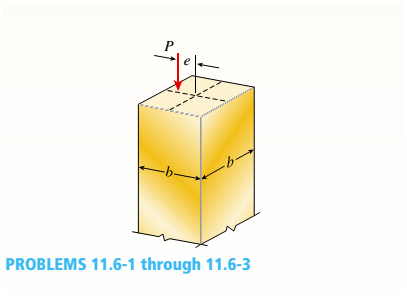
Chapter 11, Problem 11.6.3P
A square aluminum bar with pinned ends carries a load P = 25 kips acting at distance e = 2,0 in. from the center (sec figure). The bar has a length E = 54 in. and modulus of elasticity E = 10,600 ksi.
If the stress in the bar is not to exceed 6 ksi, what is the minimum permissible width bminof the bar?
Expert Solution & Answer

Trending nowThis is a popular solution!

Students have asked these similar questions
In a structural reliability problem, the resistance (capacity) R and load effect (demand) S random variables
associated with a failure mode of the structure of interest are normally distributed and statistically
independent with the following probability distribution parameters (or statistics) in consistent units:
MR = 12, σR = 3
μs = 5, σs = 2
(a) Determine the exact probability of failure pF ·
The resistance R and load effect S for a given failure mode are statistically independent random variables
with marginal PDF's
1
fR (r) =
0≤r≤100
100'
fs(s)=0.05e-0.05s
(a) Determine the probability of failure by computing the probability content of the failure domain defined
as {r
Please solve this problem as soon as possible My ID# 016948724
Chapter 11 Solutions
Mechanics of Materials (MindTap Course List)
Ch. 11 - A rigid bar of length L is supported by a linear...Ch. 11 - The figure shows an idealized structure consisting...Ch. 11 - -2-3. Two rigid bars are connected with a...Ch. 11 - Repeat Problem 11.2-3 assuming that R= 10 kN ·...Ch. 11 - The figure shows an idealized structure consisting...Ch. 11 - An idealized column consists of rigid bar ABCD...Ch. 11 - An idealized column is made up of rigid segments...Ch. 11 - The figure shows an idealized structure consisting...Ch. 11 - The figure shows an idealized structure consisting...Ch. 11 - The figure shows an idealized structure consisting...
Ch. 11 - The figure shows an idealized structure consisting...Ch. 11 - Rigid column ABCD has an elastic support at B with...Ch. 11 - An idealized column is made up of rigid bars ABC...Ch. 11 - An idealized column is composed of rigid bars ABC...Ch. 11 - Repeat Problem 11.2-14 using L = 12 ft, ß = 0.25...Ch. 11 - An idealized column is composed of rigid bars ABC...Ch. 11 - Column AB has a pin support at A,a roller support...Ch. 11 - Slender column ABC is supported at A and C and is...Ch. 11 - Calculate the critical load PCTfor a W 8 × 35...Ch. 11 - Solve the preceding problem for a W 250 × 89 steel...Ch. 11 - Solve Problem 11.3-3 for a W 10 × 45 steel column...Ch. 11 - A horizontal beam AB is pin-supported at end A and...Ch. 11 - A column ABC is supported at ends A and C and...Ch. 11 - Find the controlling buckling load (kN) for the...Ch. 11 - A column, pinned at top and bottom, is made up of...Ch. 11 - Repeat Problem 11.3-9. Use two C 150 × 12.2 steel...Ch. 11 - A horizontal beam AB is pin-supported at end A and...Ch. 11 - -12 A horizontal beam AB is supported at end A and...Ch. 11 - A horizontal beam AB has a sliding support at end...Ch. 11 - A slender bar AB with pinned ends and length L is...Ch. 11 - A rectangular column with cross-sectional...Ch. 11 - .16 Three identical, solid circular rods, each of...Ch. 11 - Three pinned-end columns of the same material have...Ch. 11 - A long slender column ABC is pinned at ends A and...Ch. 11 - The roof over a concourse at an airport is...Ch. 11 - The hoisting arrangement for lifting a large pipe...Ch. 11 - A pinned-end strut of aluminum (E = 10,400 ksi)...Ch. 11 - The cross section of a column built up of two...Ch. 11 - The truss ABC shown in the figure supports a...Ch. 11 - A truss ABC supports a load W at joint B, as shown...Ch. 11 - An S6 × 12.5 steel cantilever beam AB is supported...Ch. 11 - The plane truss shown in the figure supports...Ch. 11 - A space truss is restrained at joints O, A,B, and...Ch. 11 - A fixed-end column with circular cross section is...Ch. 11 - A cantilever aluminum column has a square tube...Ch. 11 - An aluminum pipe column (E = 10,400 ksi) with a...Ch. 11 - Solve the preceding problem for a steel pipe...Ch. 11 - A wide-flange steel column (E = 30 × l06 psi) of...Ch. 11 - Prob. 11.4.6PCh. 11 - The upper end of a WE × 21 wide-flange steel...Ch. 11 - A vertical post AB is embedded in a concrete...Ch. 11 - The horizontal beam ABC shown in the figure is...Ch. 11 - The roof beams of a warehouse are supported by...Ch. 11 - Determine the critical load Pcrand the equation of...Ch. 11 - A fixed-pinned column is a W310 × 21 steel shape...Ch. 11 - Find the Controlling buckling load (kips) for the...Ch. 11 - Prob. 11.4.14PCh. 11 - A rigid L-shaped frame is supported by a steel...Ch. 11 - An aluminum tube AB with a circular cross section...Ch. 11 - The frame ABC consists of two members AB and BC...Ch. 11 - An aluminum bar having a rectangular cross section...Ch. 11 - ‘11.5-2 A steel bar having a square cross section...Ch. 11 - A simply supported slender column is subjected to...Ch. 11 - A brass bar of a length L = 0.4 m is loaded at end...Ch. 11 - Determine the bending moment M in the pinned-end...Ch. 11 - Plot the load-deflection diagram for a pinned-end...Ch. 11 - Solve the preceding problem for a column with e =...Ch. 11 - A wide-flange member (W200 × 22.5) is compressed...Ch. 11 - A wide-f hinge member (W 10 × 30) is compressed by...Ch. 11 - Solve the preceding problem (W 250 × 44.8) if the...Ch. 11 - The column shown in the figure is fixed at the...Ch. 11 - An aluminum box column with a square cross section...Ch. 11 - Solve the preceding problem for an aluminum column...Ch. 11 - A steel post /t if with a hollow circular cross...Ch. 11 - A frame ABCD is constructed of steel wide-flange...Ch. 11 - A steel bar has a square cross section of width b...Ch. 11 - ]11.6-2 A brass bar (E = 100 GPa) with a square...Ch. 11 - A square aluminum bar with pinned ends carries a...Ch. 11 - A pinned-and column of a length L = 2A m is...Ch. 11 - A pinned-end strut of a length L = 5.2 ft is...Ch. 11 - A circular aluminum tube with pinned ends supports...Ch. 11 - A steel W 12 × 35 column is pin-supported at the...Ch. 11 - A steel W 310 x 52 column is pin-supported at the...Ch. 11 - A steel column (E = 30 x 103 ksi) with pinned ends...Ch. 11 - A W410 × S5 steel column is compressed by a force...Ch. 11 - A steel column ( E = 30 X 103 ksi) that is fixed...Ch. 11 - AW310 × 74 wide-flange steel column with length L...Ch. 11 - A pinned-end column with a length L = 18 ft is...Ch. 11 - The wide-flange, pinned-end column shown in the...Ch. 11 - A W14 × 53 wide-flange column of a length L = 15...Ch. 11 - A wide-flange column with a bracket is fixed at...Ch. 11 - Determine the allowable axial load Pallowa W 10 X...Ch. 11 - Determine the allowable axial load Pallowfor a W...Ch. 11 - Determine the allowable axial load Pallowfor a W...Ch. 11 - Select a steel wide-flange column of a nominal...Ch. 11 - Prob. 11.9.5PCh. 11 - Select a steel wide-flange column of a nominal...Ch. 11 - Prob. 11.9.7PCh. 11 - Determine the allowable axial load Pallowfor a...Ch. 11 - Determine the allowable axial load Pallowfor a...Ch. 11 - Determine the allowable axial load Pallowfor a...Ch. 11 - -11 Determine the maximum permissible length...Ch. 11 - Determine the maximum permissible length Lmaxfor a...Ch. 11 - A steel pipe column with pinned ends supports an...Ch. 11 - The steel columns used in a college recreation...Ch. 11 - A W8 × 28 steel wide-flange column with pinned...Ch. 11 - Prob. 11.9.16PCh. 11 - Prob. 11.9.17PCh. 11 - Prob. 11.9.18PCh. 11 - Prob. 11.9.19PCh. 11 - Prob. 11.9.20PCh. 11 - Prob. 11.9.21PCh. 11 - An aluminum pipe column (alloy 2014-T6) with...Ch. 11 - Prob. 11.9.23PCh. 11 - Prob. 11.9.24PCh. 11 - Prob. 11.9.25PCh. 11 - Prob. 11.9.26PCh. 11 - Prob. 11.9.27PCh. 11 - Prob. 11.9.28PCh. 11 - Prob. 11.9.29PCh. 11 - Prob. 11.9.30PCh. 11 - A wood column with, a rectangular cross section...Ch. 11 - Prob. 11.9.32PCh. 11 - Prob. 11.9.33PCh. 11 - A square wood column with side dimensions b (see...Ch. 11 - A square wood column with side dimensions b (see...Ch. 11 - Prob. 11.9.36P
Knowledge Booster


Learn more about
Need a deep-dive on the concept behind this application? Look no further. Learn more about this topic, mechanical-engineering and related others by exploring similar questions and additional content below.Similar questions
- The gears shown in the figure have a diametral pitch of 2 teeth per inch and a 20° pressure angle. The pinion rotates at 1800 rev/min clockwise and transmits 200 hp through the idler pair to gear 5 on shaft c. What forces do gears 3 and 4 transmit to the idler shaft? TS I y 18T 32T This a 12 x 18T C 48T 5arrow_forwardQuestion 1. Draw 3 teeth for the following pinion and gear respectively. The teeth should be drawn near the pressure line so that the teeth from the pinion should mesh those of the gear. Drawing scale (1:1). Either a precise hand drawing or CAD drawing is acceptable. Draw all the trajectories of the involute lines and the circles. Specification: 18tooth pinion and 30tooth gear. Diameter pitch=P=6 teeth /inch. Pressure angle:20°, 1/P for addendum (a) and 1.25/P for dedendum (b). For fillet, c=b-a.arrow_forward5. The figure shows a gear train. There is no friction at the bearings except for the gear tooth forces. The material of the milled gears is steel having a Brinell hardness of 170. The input shaft speed (n2) is 800 rpm. The face width and the contact angle for all gears are 1 in and 20° respectively. In this gear set, the endurance limit (Se) is 15 kpsi and nd (design factor) is 2. (a) Find the revolution speed of gear 5. (b) Determine whether each gear satisfies the design factor of 2.0 for bending fatigue. (c) Determine whether each gear satisfies the design factor of 2.0 for surface fatigue (contact stress). (d) According to the computation results of the questions (b) and (c), explain the possible failure mechanisms for each gear. N4=28 800rpm N₁=43 N5=34 N₂=14 P(diameteral pitch)=8 for all gears Coupled to 2.5hp motorarrow_forward
- 1. The rotating steel shaft is simply supported by bearings at points of B and C, and is driven by a spur gear at D, which has a 6-in pitch diameter. The force F from the drive gear acts at a pressure angle of 20°. The shaft transmits a torque to point A of TA =3000 lbĘ in. The shaft is machined from steel with Sy=60kpsi and Sut=80 kpsi. (1) Draw a shear force diagram and a bending moment diagram by F. According to your analysis, where is the point of interest to evaluate the safety factor among A, B, C, and D? Describe the reason. (Hint: To find F, the torque Tд is generated by the tangential force of F (i.e. Ftangential-Fcos20°) When n=2.5, K=1.8, and K₁ =1.3, determine the diameter of the shaft based on (2) static analysis using DE theory (note that fatigue stress concentration factors need to be used for this question because the loading condition is fatigue) and (3) a fatigue analysis using modified Goodman. Note) A standard diameter is not required for the questions. 10 in Darrow_forward3 N2=28 P(diametral pitch)=8 for all gears Coupled to 25 hp motor N3=34 Full depth spur gears with pressure angle=20° N₂=2000 rpm (1) Compute the circular pitch, the center-to-center distance, and base circle radii. (2) Draw the free body diagram of gear 3 and show all the forces and the torque. (3) In mounting gears, the center-to-center distance was reduced by 0.1 inch. Calculate the new values of center-to-center distance, pressure angle, base circle radii, and pitch circle diameters. (4)What is the new tangential and radial forces for gear 3? (5) Under the new center to center distance, is the contact ratio (mc) increasing or decreasing?arrow_forward2. A flat belt drive consists of two 4-ft diameter cast-iron pulleys spaced 16 ft apart. A power of 60 hp is transmitted by a pulley whose speed is 380 rev/min. Use a service factor (Ks) pf 1.1 and a design factor 1.0. The width of the polyamide A-3 belt is 6 in. Use CD=1. Answer the following questions. (1) What is the total length of the belt according to the given geometry? (2) Find the centrifugal force (Fc) applied to the belt. (3) What is the transmitted torque through the pulley system given 60hp? (4) Using the allowable tension, find the force (F₁) on the tight side. What is the tension at the loose side (F2) and the initial tension (F.)? (5) Using the forces, estimate the developed friction coefficient (f) (6) Based on the forces and the given rotational speed, rate the pulley set. In other words, what is the horse power that can be transmitted by the pulley system? (7) To reduce the applied tension on the tight side, the friction coefficient is increased to 0.75. Find out the…arrow_forward
- The tooth numbers for the gear train illustrated are N₂ = 24, N3 = 18, №4 = 30, №6 = 36, and N₁ = 54. Gear 7 is fixed. If shaft b is turned through 5 revolutions, how many turns will shaft a make? a 5 [6] barrow_forwardCE-112 please solve this problem step by step and give me the correct answerarrow_forwardCE-112 please solve this problem step by step and give me the correct answerarrow_forward
- CE-112 solve this problem step by step and give me the correct answer pleasearrow_forwardPlease do not use any AI tools to solve this question. I need a fully manual, step-by-step solution with clear explanations, as if it were done by a human tutor. No AI-generated responses, please.arrow_forwardPlease do not use any AI tools to solve this question. I need a fully manual, step-by-step solution with clear explanations, as if it were done by a human tutor. No AI-generated responses, please.arrow_forward
arrow_back_ios
SEE MORE QUESTIONS
arrow_forward_ios
Recommended textbooks for you
 Mechanics of Materials (MindTap Course List)Mechanical EngineeringISBN:9781337093347Author:Barry J. Goodno, James M. GerePublisher:Cengage Learning
Mechanics of Materials (MindTap Course List)
Mechanical Engineering
ISBN:9781337093347
Author:Barry J. Goodno, James M. Gere
Publisher:Cengage Learning
EVERYTHING on Axial Loading Normal Stress in 10 MINUTES - Mechanics of Materials; Author: Less Boring Lectures;https://www.youtube.com/watch?v=jQ-fNqZWrNg;License: Standard YouTube License, CC-BY