
Concept explainers
Videos
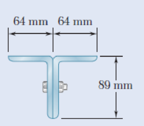
Two 89 × 64-mm angles are bolted together as shown for use as a column of 2.4-m effective length to carry a centric load of 325 kN. Knowing that the angles available have thicknesses of 6.4 mm, 9.5 mm, and 12.7 mm, use allowable stress design to determine the lightest angles that can be used. Use σY = 250 MPa and E = 200 GPa.
Fig. P10.84
Find the lightest angles that can be used.
Answer to Problem 84P
The lightest angle that can be used for the design is
Explanation of Solution
Given information:
The effective length of the column is
The allowable yield strength of the steel is
The modulus of elasticity of the steel is
The centric load acting in the column is
Calculation:
Consider the thickness of the angle section as 9.5 mm.
Refer to Appendix C “Properties of Rolled-Steel Shapes” in the textbook.
For
The cross sectional area of the angle (A) is
The moment of inertia in x-axis is
The moment of inertia in y-axis is
The centroid distance from the flange in x-axis is
The area of the two angle section is
The moment of inertia in x-axis is
Find the moment of inertia in y-axis using the relation.
Substitute
The minimum moment of inertia is
Find the minimum radius of gyration (r) using the relation.
Substitute
Find the slenderness ratio
Here, the modulus of elasticity of the material is E and the allowable yield strength is
Substitute 200 GPa for E and 250 MPa for
Find the ratio of effective length
Find the effective stress
Substitute 200 GPa for E and 97.22 for
Find the critical stress
Substitute 250 MPa for
Calculate the allowable stress
Substitute 151.472 MPa for
Calculate the allowable load
Substitute 90.702 MPa for
The centric load is greater than the allowable load. Hence, the design is unsafe.
Consider the thickness of the angle section as 12.7 mm.
Refer to Appendix C “Properties of Rolled-Steel Shapes” in the textbook.
For
The cross sectional area of the angle (A) is
The moment of inertia in x-axis is
The moment of inertia in y-axis is
The centroid distance from the flange in x-axis is
The area of the two angle section is
The moment of inertia in x-axis is
Find the moment of inertia in y-axis using the relation.
Substitute
The minimum moment of inertia is
Find the minimum radius of gyration (r) using the relation.
Substitute
Find the slenderness ratio
Here, the modulus of elasticity of the material is E and the allowable yield strength is
Substitute 200 GPa for E and 250 MPa for
Find the ratio of effective length
Find the effective stress
Substitute 200 GPa for E and 95.12 for
Find the critical stress
Substitute 250 MPa for
Calculate the allowable stress
Substitute 154.753 MPa for
Calculate the allowable load
Substitute 92.667 MPa for
The centric load is less than the allowable load. Hence, the design is unsafe.
Therefore, the lightest angle that can be used for the design is
Want to see more full solutions like this?
Chapter 10 Solutions
EBK MECHANICS OF MATERIALS


- This is an exam review question. The answer is Pmin = 622.9 lb but whyarrow_forwardPlease do not use any AI tools to solve this question. I need a fully manual, step-by-step solution with clear explanations, as if it were done by a human tutor. No AI-generated responses, please.arrow_forwardPlease do not use any AI tools to solve this question. I need a fully manual, step-by-step solution with clear explanations, as if it were done by a human tutor. No AI-generated responses, please.arrow_forward
- Please do not use any AI tools to solve this question. I need a fully manual, step-by-step solution with clear explanations, as if it were done by a human tutor. No AI-generated responses, please.arrow_forwardThis is an old practice exam. Fce = 110lb and FBCD = 62 lb but whyarrow_forwardQuiz/An eccentrically loaded bracket is welded to the support as shown in Figure below. The load is static. The weld size for weld w1 is h1 = 4mm, for w2 h2 = 6mm, and for w3 is h3 =6.5 mm. Determine the safety factor (S.f) for the welds. F=29 kN. Use an AWS Electrode type (E100xx). 163 mm S 133 mm 140 mm Please solve the question above I solved the question but I'm sure the answer is wrong the link : https://drive.google.com/file/d/1w5UD2EPDiaKSx3W33aj Rv0olChuXtrQx/view?usp=sharingarrow_forward
- Q2: (15 Marks) A water-LiBr vapor absorption system incorporates a heat exchanger as shown in the figure. The temperatures of the evaporator, the absorber, the condenser, and the generator are 10°C, 25°C, 40°C, and 100°C respectively. The strong liquid leaving the pump is heated to 50°C in the heat exchanger. The refrigerant flow rate through the condenser is 0.12 kg/s. Calculate (i) the heat rejected in the absorber, and (ii) the COP of the cycle. Yo 8 XE-V lo 9 Pc 7 condenser 5 Qgen PG 100 Qabs Pe evaporator PRV 6 PA 10 3 generator heat exchanger 2 pump 185 absorberarrow_forwardQ5:(? Design the duct system of the figure below by using the balanced pressure method. The velocity in the duct attached to the AHU must not exceed 5m/s. The pressure loss for each diffuser is equal to 10Pa. 100CFM 100CFM 100CFM ☑ ☑ 40m AHU -16m- 8m- -12m- 57m 250CFM 40m -14m- 26m 36m ☑ 250CFMarrow_forwardA mass of ideal gas in a closed piston-cylinder system expands from 427 °C and 16 bar following the process law, pv1.36 = Constant (p times v to the power of 1.36 equals to a constant). For the gas, initial : final pressure ratio is 4:1 and the initial gas volume is 0.14 m³. The specific heat of the gas at constant pressure, Cp = 0.987 kJ/kg-K and the specific gas constant, R = 0.267 kJ/kg.K. Determine the change in total internal energy in the gas during the expansion. Enter your numerical answer in the answer box below in KILO JOULES (not in Joules) but do not enter the units. (There is no expected number of decimal points or significant figures).arrow_forward
- my ID# 016948724. Please solve this problem step by steparrow_forwardMy ID# 016948724 please find the forces for Fx=0: fy=0: fz=0: please help me to solve this problem step by steparrow_forwardMy ID# 016948724 please solve the proble step by step find the forces fx=o: fy=0; fz=0; and find shear moment and the bending moment diagran please draw the diagram for the shear and bending momentarrow_forward
 Automotive Technology: A Systems Approach (MindTa...Mechanical EngineeringISBN:9781133612315Author:Jack Erjavec, Rob ThompsonPublisher:Cengage Learning
 Mechanics of Materials (MindTap Course List)Mechanical EngineeringISBN:9781337093347Author:Barry J. Goodno, James M. GerePublisher:Cengage Learning
 International Edition---engineering Mechanics: St...Mechanical EngineeringISBN:9781305501607Author:Andrew Pytel And Jaan KiusalaasPublisher:CENGAGE L