
Statics and Mechanics of Materials (5th Edition)
5th Edition
ISBN: 9780134382593
Author: Russell C. Hibbeler
Publisher: PEARSON
expand_more
expand_more
format_list_bulleted
Concept explainers
Videos
Textbook Question
Chapter 10.3, Problem 10P
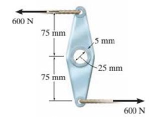
The link acts as part of the elevator control for a small airplane. If the attached aluminum tube has an inner diameter of 25 mm and a wall thickness of 5 mm. determine the maximum shear stress in the tube when the cable force of 600 N is applied to the cables. Also, sketch the shear-stress distribution over the cross section.
Prob. 10-10
Expert Solution & Answer
Want to see the full answer?
Check out a sample textbook solution
Students have asked these similar questions
A spring package with two springs and an external force, 200N. The short spring has a loin of 35 mm. Constantly looking for spring for short spring so that total compression is 35 mm (d). Known values: Long spring: Short spring:C=3.98 N/mm Lo=65mmLo=87.4mmF=c·fTotal compression is same for both spring. 200 = (3.98(c1) × 35) + (c₂ × 35)
200 = 139.3 + 35c₂
200 - 139.3 = 35c₂
60.7 = 35c₂
c₂ = 60.7/35
Short spring (c₂) = 1.73 N/mm
According to my study book, the correct answer is 4.82N/mm
What is wrong with the calculating?
What is the reason for this composition?
Homework: ANOVA Table for followed design
B
AB
Dr
-1
-1
1
(15.18,12)
1
-1
-1
(45.48.51)
-1
1
-1
(25,28,19)
1
1
(75.75,81)
Chapter 10 Solutions
Statics and Mechanics of Materials (5th Edition)
Ch. 10.3 - Determine the internal torque at each section and...Ch. 10.3 - Determine the internal torque at each section and...Ch. 10.3 - Prob. 3PPCh. 10.3 - Prob. 4PPCh. 10.3 - Prob. 1FPCh. 10.3 - The hollow circular shaft is subjected to an...Ch. 10.3 - Prob. 3FPCh. 10.3 - Prob. 4FPCh. 10.3 - Determine the maximum shear stress in the shaft at...Ch. 10.3 - Prob. 6FP
Ch. 10.3 - The solid 50-mm-diameter shaft is subjected to the...Ch. 10.3 - Prob. 8FPCh. 10.3 - Prob. 1PCh. 10.3 - Prob. 2PCh. 10.3 - A shaft is made of an aluminum alloy having an...Ch. 10.3 - The copper pipe has an outer diameter of 40 mm and...Ch. 10.3 - The copper pipe has an outer diameter of 2.50 in....Ch. 10.3 - The solid aluminum shaft has a diameter of 50 mm...Ch. 10.3 - The solid aluminum shaft has a diameter of 50 mm....Ch. 10.3 - The solid 30-mm-diameter shaft is used to transmit...Ch. 10.3 - The solid shaft is fixed to the support at C and...Ch. 10.3 - The link acts as part of the elevator control for...Ch. 10.3 - The assembly consists of two sections of...Ch. 10.3 - The shaft has an outer diameter of 100 mm and an...Ch. 10.3 - Prob. 13PCh. 10.3 - Prob. 14PCh. 10.3 - Prob. 15PCh. 10.3 - Prob. 16PCh. 10.3 - The rod has a diameter of 1 in. and a weight of 10...Ch. 10.3 - Prob. 18PCh. 10.3 - Prob. 19PCh. 10.3 - Prob. 20PCh. 10.3 - Prob. 21PCh. 10.3 - The 60-mm-diametcr solid shaft is subjected to the...Ch. 10.3 - Prob. 23PCh. 10.3 - The 60-mm-diameter solid shaft is subjected to the...Ch. 10.3 - Prob. 25PCh. 10.3 - The pump operates using the motor that has a power...Ch. 10.3 - Prob. 27PCh. 10.3 - Prob. 28PCh. 10.3 - Prob. 29PCh. 10.3 - The gear motor can develop 2 hp when it turns at...Ch. 10.3 - Prob. 31PCh. 10.3 - The 6-hp reducer motor can turn at 1200 rev/min....Ch. 10.3 - Prob. 33PCh. 10.3 - Prob. 34PCh. 10.4 - The 60-mm-diameter steel shaft is subjected to the...Ch. 10.4 - Prob. 10FPCh. 10.4 - The hollow 6061-T6 aluminum shaft has an outer and...Ch. 10.4 - A series of gears are mounted on the...Ch. 10.4 - Prob. 13FPCh. 10.4 - The 80-mm-diameter shaft is made of steel. If it...Ch. 10.4 - The propellers of a ship are connected to an A-36...Ch. 10.4 - Prob. 36PCh. 10.4 - The splined ends and gears attached to the A992...Ch. 10.4 - Prob. 38PCh. 10.4 - The 60-mm-diameter shaft is made of 6061-T6...Ch. 10.4 - The 60-mm-diameter shaft is made of 6061-T6...Ch. 10.4 - Prob. 41PCh. 10.4 - Prob. 42PCh. 10.4 - Gear B supplies 15 kW of power, while gears A, C,...Ch. 10.4 - Prob. 44PCh. 10.4 - The turbine develops 150 kW of power, which is...Ch. 10.4 - Prob. 46PCh. 10.4 - Prob. 47PCh. 10.4 - Prob. 48PCh. 10.4 - The A 992 steel shaft has a diameter of 50 mm and...Ch. 10.4 - The turbine develops 300 kW of power, which is...Ch. 10.4 - Prob. 51PCh. 10.4 - The device shown is used to mix soils in order to...Ch. 10.4 - The 6-in.-diameter L-2 steel shaft on the turbine...Ch. 10.4 - The A-36 hollow steel shaft is 2 m long and has an...Ch. 10.4 - The A-36 solid steel shaft is 3 m long and has a...Ch. 10.4 - Prob. 56PCh. 10.4 - Prob. 57PCh. 10.4 - Prob. 58PCh. 10.4 - The tubular drive shaft for the propeller of a...Ch. 10.4 - The 60-mm diameter solid shaft is made of 2014-T6...Ch. 10.4 - Prob. 61PCh. 10.5 - The steel shaft has a diameter of 40 mm and is...Ch. 10.5 - The A992 steel shaft has a diameter of 60 mm and...Ch. 10.5 - The steel shaft is made from two segments: AC has...Ch. 10.5 - The bronze C86100 pipe has an outer diameter of...Ch. 10.5 - The bronze C86100 pipe has an outer diameter of...Ch. 10.5 - Prob. 67PCh. 10.5 - Prob. 68PCh. 10.5 - The Am1004-T61 magnesium tube is bonded to the...Ch. 10.5 - The Am1004-T61 magnesium tube is bonded to the...Ch. 10.5 - The two shafts are made of A-36 steel. Each has a...Ch. 10.5 - Prob. 72PCh. 10.5 - Prob. 73PCh. 10.5 - Prob. 74PCh. 10.5 - Prob. 75PCh. 10.5 - The composite shaft consists of a mid-section that...Ch. 10.5 - Prob. 77PCh. 10.5 - The tapered shaft is confined by the fixed...Ch. 10.5 - Prob. 79PCh. 10 - The shaft is made of A992 steel and has an...Ch. 10 - The shaft is made of A992 steel and has an...Ch. 10 - The A-36 steel circular tube is subjected to a...Ch. 10 - Prob. 4RPCh. 10 - Prob. 5RPCh. 10 - Prob. 6RPCh. 10 - Prob. 7RPCh. 10 - Prob. 8RPCh. 10 - The 60-mm-diameter shaft rotates at 300 rev/min....
Knowledge Booster


Learn more about
Need a deep-dive on the concept behind this application? Look no further. Learn more about this topic, mechanical-engineering and related others by exploring similar questions and additional content below.Similar questions
- 20. [Ans. 9; 71.8 mm] A semi-elliptical laminated spring is made of 50 mm wide and 3 mm thick plates. The length between the supports is 650 mm and the width of the band is 60 mm. The spring has two full length leaves and five graduated leaves. If the spring carries a central load of 1600 N, find: 1. Maximum stress in full length and graduated leaves for an initial condition of no stress in the leaves. 2. The maximum stress if the initial stress is provided to cause equal stress when loaded. [Ans. 590 MPa ; 390 MPa ; 450 MPa ; 54 mm] 3. The deflection in parts (1) and (2).arrow_forwardQ6/ A helical square section spring is set inside another, the outer spring having a free length of 35 mm greater than the inner spring. The dimensions of each spring are as follows: Mean diameter (mm) Side of square section (mm) Active turns Outer Inner Spring Spring 120 70 8 7 20 15 Determine the (1) Maximum deflection of the two springs and (2) Equivalent spring rate of the two springs after sufficient load has been applied to deflect the outer spring 60 mm. Use G = 83 GN/m².arrow_forwardQ2/ The bumper springs of a railway carriage are to be made of rectangular section wire. The ratio of the longer side of the wire to its shorter side is 1.5, and the ratio of mean diameter of spring to the longer side of wire is nearly equal to 6. Three such springs are required to bring to rest a carriage weighing 25 kN moving with a velocity of 75 m/min with a maximum deflection of 200 mm. Determine the sides of the rectangular section of the wire and the mean diameter of coils when the shorter side is parallel to the axis of the spring. The allowable shear stress is not to exceed 300 MPa and G = 84 kN/mm². Q6/ A belicalarrow_forward
- 11. A load of 2 kN is dropped axially on a close coiled helical spring, from a height of 250 mm. The spring has 20 effective turns, and it is made of 25 mm diameter wire. The spring index is 8. Find the maximum shear stress induced in the spring and the amount of compression produced. The modulus of rigidity for the material of the spring wire is 84 kN/mm². [Ans. 287 MPa; 290 mm]arrow_forwardWhat is the reason for this composition?arrow_forwardHomework: ANOVA Table for followed design B AB Dr -1 -1 1 (15.18,12) 1 -1 -1 (45.48.51) -1 1 -1 (25,28,19) 1 1 (75.75,81)arrow_forward
- S B Pin 6 mm Garrow_forwardMid-Term Exam 2024/2025 Post graduate/Applied Mechanics- Metallurgy Q1/ State the type of fault in the following case, and state the structure in which it will appear. АВСАВСВАСВАСАВСАВСarrow_forwardالثانية Babakt Momentum equation for Boundary Layer S SS -Txfriction dray Momentum equation for Boundary Layer What laws are important for resolving issues 2 How to draw. 3 What's Point about this.arrow_forward
- R αι g The system given on the left, consists of three pulleys and the depicted vertical ropes. Given: ri J₁, m1 R = 2r; απ r2, J2, m₂ m1; m2; M3 J1 J2 J3 J3, m3 a) Determine the radii 2 and 3.arrow_forwardB: Solid rotating shaft used in the boat with high speed shown in Figure. The amount of power transmitted at the greatest torque is 224 kW with 130 r.p.m. Used DE-Goodman theory to determine the shaft diameter. Take the shaft material is annealed AISI 1030, the endurance limit of 18.86 kpsi and a factor of safety 1. Which criterion is more conservative? Note: all dimensions in mm. 1 AA Motor 300 Thrust Bearing Sprocket 100 9750 เอarrow_forwardQ2: The plate material of a pressure vessel is AISI 1050 QT 205 °C. The plate is rolled to a diameter of 1.2 m. The two sides of the plate are connected via a riveted joint as shown below. If the rivet material is G10500 with HB=197 and all rivet sizes M31. Find the required rivet size when the pressure vessel is subjected to an internal pressure of 500 MPa. Take safety factor = 2. 1.2m A B' A Chope olm 10.5 0.23 hopearrow_forward
arrow_back_ios
SEE MORE QUESTIONS
arrow_forward_ios
Recommended textbooks for you
 Elements Of ElectromagneticsMechanical EngineeringISBN:9780190698614Author:Sadiku, Matthew N. O.Publisher:Oxford University Press
 Mechanics of Materials (10th Edition)Mechanical EngineeringISBN:9780134319650Author:Russell C. HibbelerPublisher:PEARSON
 Thermodynamics: An Engineering ApproachMechanical EngineeringISBN:9781259822674Author:Yunus A. Cengel Dr., Michael A. BolesPublisher:McGraw-Hill Education
 Control Systems EngineeringMechanical EngineeringISBN:9781118170519Author:Norman S. NisePublisher:WILEY
 Mechanics of Materials (MindTap Course List)Mechanical EngineeringISBN:9781337093347Author:Barry J. Goodno, James M. GerePublisher:Cengage Learning
 Engineering Mechanics: StaticsMechanical EngineeringISBN:9781118807330Author:James L. Meriam, L. G. Kraige, J. N. BoltonPublisher:WILEY
Elements Of Electromagnetics
Mechanical Engineering
ISBN:9780190698614
Author:Sadiku, Matthew N. O.
Publisher:Oxford University Press
Mechanics of Materials (10th Edition)
Mechanical Engineering
ISBN:9780134319650
Author:Russell C. Hibbeler
Publisher:PEARSON
Thermodynamics: An Engineering Approach
Mechanical Engineering
ISBN:9781259822674
Author:Yunus A. Cengel Dr., Michael A. Boles
Publisher:McGraw-Hill Education
Control Systems Engineering
Mechanical Engineering
ISBN:9781118170519
Author:Norman S. Nise
Publisher:WILEY
Mechanics of Materials (MindTap Course List)
Mechanical Engineering
ISBN:9781337093347
Author:Barry J. Goodno, James M. Gere
Publisher:Cengage Learning
Engineering Mechanics: Statics
Mechanical Engineering
ISBN:9781118807330
Author:James L. Meriam, L. G. Kraige, J. N. Bolton
Publisher:WILEY
Pressure Vessels Introduction; Author: Engineering and Design Solutions;https://www.youtube.com/watch?v=Z1J97IpFc2k;License: Standard youtube license