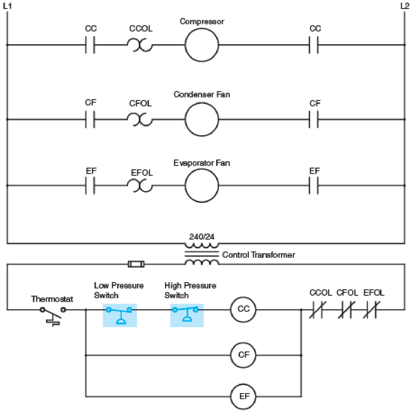
Refer to the circuit shown in Figure 10–6. Assume that when the thermostat contact closes the compressor does not start, but the condenser fan and evaporator fan do start. When troubleshooting the circuit, a voltmeter connected across the compressor contactor coil CC indicates 0 volts. A voltmeter connected across the high-pressure switch indicates 0 volts, and a voltmeter placed across the thermostat contact indicates 0 volts. When the voltmeter is connected across the low-pressure switch it indicates 24 volts. Which of the following conditions could cause this problem?
a. The refrigerant pressure is too high.
b. The compressor contactor coil is open.
c. The refrigerant pressure is too low.
d. The thermostat contact is open.

Fig. 10–6 Pressure switches are often used in air-conditioning circuits.
Want to see the full answer?
Check out a sample textbook solution
Chapter 10 Solutions
Electric Motor Control
- The circuit shown in the figure below is at steady state before the switch closes at time t=0s. Determine an expression for the capacitor voltage V for t≥0s.arrow_forwardneed a soluarrow_forwardQ1. A 450 V, 50 Hz, 1450 r.p.m., 25 kW, star-connected three-phase induction motor delivers constant (rated) torque at all speeds. The motor equivalent circuit parameters at rated frequency are R1=0.12, R2 = 0.17 2, X₁ = 0.3 2, X2 = 0.5 2, Xm = 23.6 2. Smooth speed variation is obtained by primary frequency control with simultaneous variation of the terminal voltage to maintain constant air-gap flux. Calculate the motor current, power factor and efficiency at one-fifth of rated speed.arrow_forward
- Q2. Drive the transformations for currents between a rotating balanced two phase (a,ẞ) winding and a pseudo stationary two phase (d,q) wingding.arrow_forwardThe formulas that should be used to solve the question are in the second picture, also B = k/n a= l/carrow_forward"I need proof in the solution and a supported source with the solution." Write a 8086 microprocessor program to clear (100) consecutive memory locations starting at offset address 8000H. Assume the data segment value equal to 3000H write an 8086 microprocessor program to add two numbers each of four bytes. The first number (least significant byte) starts at memory offset 0500H and the second number (least significant byte) start at offset memory address 0600H Assume the data segment value equal to 0100H.Store the result at memory offset starts 0800H write a program to move a block of 100 numbers consecutive bytes of data strings at offset address 8000 H in memory to another block of memory locations starting at offset address A000 H. assume that both blocks are in the same data segment value 3000H (25 Marks) Write a program to multiply AX by (10.5) using shift instructionarrow_forward
- solve simultaneous equation for the analogue computer given in figurearrow_forward5.2 Explain how a rotating commutator winding may be represented as an equivalent pseudo-stationary coil along the brush axis, and describe the special properties of this type of coil. Write the general voltage and torque equations for the two-pole commutator machine shown in Fig. Prob. 5.2. Explain how the rotational inductance coefficients (G) may be obtained in terms of the Land 1 inductance coefficients. q-axis 9 Fig. Prob. 5.2 d-axisarrow_forward(b) Derive the steady state voltage equations for a compensated metadyne generator shown in Fig.1 A 2kW, 200V, 1500rpm, 2-pole fully compensated metadyne generator has the following parameters: Field self inductance and resistance 30Η, 200Ω Armature self inductance and resistance 0.067, 1 Ω - Field armature mutual inductance 1.2H Calculate for steady state operation, the field current and power gain at rated output. 19-axis १६ Fig. 1 Laxis -arrow_forward

 Power System Analysis and Design (MindTap Course ...Electrical EngineeringISBN:9781305632134Author:J. Duncan Glover, Thomas Overbye, Mulukutla S. SarmaPublisher:Cengage Learning
 Electricity for Refrigeration, Heating, and Air C...Mechanical EngineeringISBN:9781337399128Author:Russell E. SmithPublisher:Cengage Learning


