
Laboratory Manual for Introductory Circuit Analysis
13th Edition
ISBN: 9780133923780
Author: Robert L. Boylestad, Gabriel Kousourou
Publisher: PEARSON
expand_more
expand_more
format_list_bulleted
Videos
Textbook Question
Chapter 10, Problem 19P
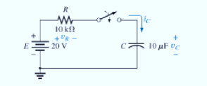
For the circuit in Fig. 10.94, composed of standard values:
a. Determine the time constant of the circuit.
b. Write the mathematical equation for the voltage
c. Determine the voltage
d. Write the equations for the current i and the voltage
e. Sketch the waveforms for
Expert Solution & Answer
Want to see the full answer?
Check out a sample textbook solution
Students have asked these similar questions
dny
dn-1y
dn-1u
dn-24
+a1
+
+ Any
=
bi
+b₂-
+ +bnu.
dtn
dtn-1
dtn-1
dtn-2
a) Let be a root of the characteristic equation
1
sn+a1sn-
+
+an
= : 0.
Show that if u(t) = 0, the differential equation has the solution y(t) = e\t.
b) Let к be a zero of the polynomial
b(s) = b₁s-1+b2sn−2+
Show that if the input is u(t)
equation that is identically zero.
=
..
+bn.
ekt, then there is a solution to the differential
For step a), use equations (2) to find the equation for the input impedance
equations (2) are V1 = jwL1I1 + jwMI2 and V2 = jwMI1 + jwL2I2
equation for the input impedance: Z1 = V1/I1 = jwL1 + (wM)2/(jwL2 + ZL)
Chapter 10 Solutions
Laboratory Manual for Introductory Circuit Analysis
Ch. 10 - a. Find the electric field strength at a point 1 m...Ch. 10 - The electric field strength is 72 newtons/coulomb...Ch. 10 - Find the capacitance of a parallel plate capacitor...Ch. 10 - How much charge is deposited on the plates of a...Ch. 10 - a. Find the electric field strength between the...Ch. 10 - A 6.8 pF parallel plate capacitor has 160 C of...Ch. 10 - Find the capacitance of a parallel plate capacitor...Ch. 10 - Repeat Problem 7 if the dielectric is...Ch. 10 - Find the distance in mils between the plates of a...Ch. 10 - The capacitance of a capacitor with a dielectric...
Ch. 10 - The plates of a parallel plate capacitor with a...Ch. 10 - A parallel plate air capacitor has a capacitance...Ch. 10 - Find the maximum voltage that can be applied...Ch. 10 - Find the distance in micrometers between the...Ch. 10 - A 22 pF capacitor has -200 ppm/C at room...Ch. 10 - What is the capacitance of a small teardrop...Ch. 10 - A large, flat, mica capacitor is labeled 471F....Ch. 10 - A small, flat, disc ceramic capacitor is labeled...Ch. 10 - For the circuit in Fig. 10.94, composed of...Ch. 10 - Repeat Problem 19 for R=100k, and compare the...Ch. 10 - For the circuit in Fig. 10.95, composed of...Ch. 10 - For the circuit in Fig. 10.96, composed of...Ch. 10 - Prob. 23PCh. 10 - The voltage across a 10 F capacitor in a series...Ch. 10 - For the R-C circuit in Fig. 10.97. composed of...Ch. 10 - For the network in Fig. 10.98. composed of...Ch. 10 - For the network in Fig.10.99.composed of standard...Ch. 10 - The 1000 F capacitor in Fig.10.100 is charged to...Ch. 10 - The capacitor in Fig. 10.101 is initially charged...Ch. 10 - Repeat Problem 29 if the initial charge is -40V.Ch. 10 - Repeat Problem 29 if the initial charge is +40V.Ch. 10 - The capacitor in Fig. 10.102 is initially charged...Ch. 10 - The capacitor in Fig. 10.103 is initially charged...Ch. 10 - The capacitor in Fig. 10.104 is initially charged...Ch. 10 - The capacitors of Fig. 10.105 are initially...Ch. 10 - Repeat Problem 35 if a 10 k resistor is placed in...Ch. 10 - Given the expression vc=140mV(1-e-t/2ms) a....Ch. 10 - For the automobile circuit of Fig. 10.106. VL must...Ch. 10 - Design the network in Fig.10.107 such that the...Ch. 10 - For the circuit in Fig. 10.108: a. Find the time...Ch. 10 - For the system in Fig. 10.109. using a DMM with a...Ch. 10 - For the circuit in Fig. 10.110: a. Find the...Ch. 10 - The capacitor in Fig. 10.111 is initially charged...Ch. 10 - The capacitors in Fig. 10.112 are initially...Ch. 10 - For the circuit in Fig. 10.113: a. Find the...Ch. 10 - The capacitor in Fig. 10.114 is initially charged...Ch. 10 - For the system in Fig. 10.115, using a DMM with a...Ch. 10 - Find the waveform for the average current if the...Ch. 10 - Find the waveform for the average current if the...Ch. 10 - Given the waveform in Fig.10.118 for the current...Ch. 10 - Find the total capacitance CT for the network in...Ch. 10 - Find the total capacitance CT for the network in...Ch. 10 - Find the steady-state voltage across and the...Ch. 10 - Find the steady-state voltage across and the...Ch. 10 - For the configuration in Fig. 10.123, determine...Ch. 10 - For the configuration in Fig.10.124, determine the...Ch. 10 - Find the energy stored by a 120 pF capacitor with...Ch. 10 - If the energy stored by a 6 F capacitor is 1200 J,...Ch. 10 - For the network in Fig. 10.125, determine the...Ch. 10 - An electronic flashgun has a 1000 F capacitor that...Ch. 10 - Using PSpice or Multisim, verify the results in...Ch. 10 - Using the initial condition operator, verify the...Ch. 10 - Using PSpice or Multisim, verify the results for...Ch. 10 - Using PSpice or Multisim, verify the results in...
Knowledge Booster


Learn more about
Need a deep-dive on the concept behind this application? Look no further. Learn more about this topic, electrical-engineering and related others by exploring similar questions and additional content below.Similar questions
- L (a) Find currents i, and b₂ 2 2 (b) Find the dependent source voltage given as Find voltages V, and (c) V₂ 5i2 (d) For each circuit element in the circuit and the two Sources, state whether they are ABSORBING OF SUPPYING Power and how much power is absorbed or Supplied. + V - 5A +lov- C/E₂ + C/E4 Vz い 5+2 + 1A C/E 5V + シュ 2A + 10Varrow_forward4) A circuit is given as shown. (a) Find currents i, and i2. (b) Find the dependent source voltage given as 5i2 (c) Find voltages V, and V₂ 2 (d) For each circuit element in the circuit and the two Sources, State whether they are ABSORBING, OF SUPPLYING POWER and how much power is absorbed or supplied. + 10V - + 4 CIES C/E + V L₁ 4 1A Y T5A GE -5V + CIES iz 2A 2 52 2 +arrow_forwardDetermine the eigenvalues and eigenvectors of using A = ( 1 -3 3 3 -5 3 6-64 Gauss eliminationarrow_forward
- 5) A circuit is given as shown (a) Find currents i₁, L2 and is . (6) Find voltages V, V2, V3 and Vy (c) For each circuit element in the circuit and the two sources, state whether they are ABSORBING SUPPLYING POWER and how much power is absorbed or supplied. + V₁ CIE, 1A +2V- C/E AS 1A + - 4A Vy+ CES CIES 2A4 + IOV +- + + V2 1 434 12V GVarrow_forwardDetermine the eigenvalues and eigenvectors of using Gauss A = -3 322 20 132 -3° 10 -2 4 eliminationarrow_forwardDetermine the eigenvalues and eigenvectors of 1-3 3 A = 3-53 6-64arrow_forward
- Consider the following transformer circuit assuming an ideal transformer. In this circuit the signal generator will provide a 10-Volt peak-to-peak sinusoidal signal at a frequency of 1.0 kHz. Assume that L₁ = 0.65 H, L2 = 0.00492 H (=4.92 mH) and that the coupling constant = 0.99925. + VG1( R1 1k N1:N2 11.5:1 12 V1 N1 N2 V2 R2 8.2 1) Find the following using the theory presented in the prelab reading: a) Start with Equations (2) of the prelab reading and show that the input impedance to an ideal transformer is given by the equation for Z1 (=V1/11) in Equations (4) of the prelab reading. Equations (2) are: V₁ = joLI₁ + jœMI₂ and V₂ = j@MI₁ +j@L₂I₂ The equation for the input impedance is: Z₁ = 1½ = jwL₁ + (WM)² jwL₂+ZL b) Assuming that Z is a real impedance, find the equations for the real and imaginary parts of Z1. c) Use your equations from part (b) to calculate the value of the input impedance (Z) at an operating frequency of 200 Hz. Assume that the load impedance is 8.2 Ohms…arrow_forwardUse: R1 = 1.5K, R2 = 5K, R3 = 1K, R4 = 2K, R5 = 2K, R6 = 1K. 40%: Find the value for Vs (in V) such as IR2 = 1mA. 40%: Find the voltage VD. 20%: simulate the circuit in Falstad (attach the link). A 1,5k B R1 Vs L 5k P2 R2 R6 E C R3 С IR2= 1mA D H4 R4 2k 2k R5arrow_forwardThe joint pdf of random variables X=1, 2 and Y=1,2,3 is Y P(X,Y)= X [0.105 0.2 0.15] 0.151 0.18arrow_forward
arrow_back_ios
SEE MORE QUESTIONS
arrow_forward_ios
Recommended textbooks for you
 Electricity for Refrigeration, Heating, and Air C...Mechanical EngineeringISBN:9781337399128Author:Russell E. SmithPublisher:Cengage Learning
Electricity for Refrigeration, Heating, and Air C...
Mechanical Engineering
ISBN:9781337399128
Author:Russell E. Smith
Publisher:Cengage Learning
L21E127 Control Systems Lecture 21 Exercise 127: State-space model of an electric circuit; Author: bioMechatronics Lab;https://www.youtube.com/watch?v=sL0LtyfNYkM;License: Standard Youtube License