EBK SYSTEM DYNAMICS
3rd Edition
ISBN: 8220100254963
Author: Palm
Publisher: MCG
expand_more
expand_more
format_list_bulleted
Concept explainers
Videos
Textbook Question
Chapter 10, Problem 10.69P
10.69 Figure P10.7 shows a system for controlling the angular position of a load.
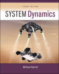
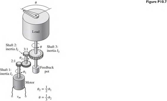
such as an antenna. Figure Pl0.69 shows the block diagram for PD control of this system using a field-controlled motor. Use the following values:
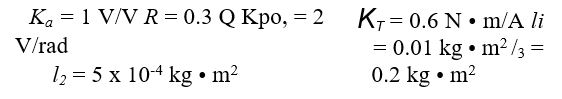
The inertia /, in the block diagram is the equivalent inertia of the entire system, as felt on the motor shaft.
- Assume that the motor inductance is very small and set L = 0. Compute 4, obtain the transfer function 0(s)/0r(s), and compute the values of the control gains Kp and Kj to meet the following specifications: < = 1 and t = 0.5 s.
Expert Solution & Answer
Want to see the full answer?
Check out a sample textbook solution
Students have asked these similar questions
2. Find a basis of solutions by the Frobenius method. Try to identify the series as expansions of
known functions.
(x + 2)²y" + (x + 2)y' - y = 0 ; Hint: Let: z = x+2
1. Find a power series solution in powers of x.
y" - y' + x²y = 0
3. Find a basis of solutions by the Frobenius method. Try to identify the series as expansions of
known functions.
8x2y" +10xy' + (x 1)y = 0
-
Chapter 10 Solutions
EBK SYSTEM DYNAMICS
Ch. 10 - Prob. 10.1PCh. 10 - 10.2 Draw the block diagram of a system using...Ch. 10 - Prob. 10.3PCh. 10 - Prob. 10.4PCh. 10 - Prob. 10.5PCh. 10 - Prob. 10.8PCh. 10 - Prob. 10.9PCh. 10 - Prob. 10.12PCh. 10 - Prob. 10.13PCh. 10 - Prob. 10.14P
Ch. 10 - Prob. 10.15PCh. 10 - Prob. 10.16PCh. 10 - Prob. 10.17PCh. 10 - Prob. 10.19PCh. 10 - Prob. 10.20PCh. 10 - Prob. 10.21PCh. 10 - Prob. 10.22PCh. 10 - Prob. 10.23PCh. 10 - Prob. 10.24PCh. 10 - Consider the PI speed control system shown in...Ch. 10 - Prob. 10.26PCh. 10 - Prob. 10.27PCh. 10 - Prob. 10.28PCh. 10 - Prob. 10.29PCh. 10 - Prob. 10.30PCh. 10 - Prob. 10.31PCh. 10 - Prob. 10.32PCh. 10 - Prob. 10.33PCh. 10 - Prob. 10.34PCh. 10 - Prob. 10.35PCh. 10 - Prob. 10.36PCh. 10 - For the designs found in part (a) of Problem...Ch. 10 - Prob. 10.39PCh. 10 - Prob. 10.40PCh. 10 - Prob. 10.41PCh. 10 - Prob. 10.44PCh. 10 - Prob. 10.45PCh. 10 - Prob. 10.46PCh. 10 - For the system shown in Figure 10.7.1, / = c = 1....Ch. 10 - Prob. 10.48PCh. 10 - Prob. 10.51PCh. 10 - Prob. 10.52PCh. 10 - Prob. 10.53PCh. 10 - Prob. 10.54PCh. 10 - Prob. 10.56PCh. 10 - Prob. 10.57PCh. 10 - Prob. 10.58PCh. 10 - Prob. 10.59PCh. 10 - Prob. 10.60PCh. 10 - Prob. 10.61PCh. 10 - Prob. 10.62PCh. 10 - Prob. 10.63PCh. 10 - Prob. 10.64PCh. 10 - Prob. 10.65PCh. 10 - Consider Example 10.6.3. Modify the diagram in...Ch. 10 - Prob. 10.67PCh. 10 - 10.68 Consider Example 10.6.4. Modify the diagram...Ch. 10 - 10.69 Figure P10.7 shows a system for controlling...Ch. 10 - A speed control system using an...Ch. 10 - Prob. 10.72PCh. 10 - Prob. 10.73PCh. 10 - Prob. 10.74PCh. 10 - Consider Example 10.7.4. Use the diagram in Figure...Ch. 10 - Prob. 10.76PCh. 10 - Refer to Figure 10.3.9, which show s a speed...Ch. 10 - For the system in Problem 10.77 part (a), create a...
Knowledge Booster


Learn more about
Need a deep-dive on the concept behind this application? Look no further. Learn more about this topic, mechanical-engineering and related others by exploring similar questions and additional content below.Similar questions
- Hello I was going over the solution for this probem and I'm a bit confused on the last part. Can you please explain to me 1^4 was used for the Co of the tubular cross section? Thank you!arrow_forwardBlood (HD = 0.45 in large diameter tubes) is forced through hollow fiber tubes that are 20 µm in diameter.Equating the volumetric flowrate expressions from (1) assuming marginal zone theory and (2) using an apparentviscosity for the blood, estimate the marginal zone thickness at this diameter. The viscosity of plasma is 1.2 cParrow_forwardQ2: Find the shear load on bolt A for the connection shown in Figure 2. Dimensions are in mm Fig. 2 24 0-0 0-0 A 180kN (10 Markarrow_forward
- determine the direction and magnitude of angular velocity ω3 of link CD in the four-bar linkage using the relative velocity graphical methodarrow_forwardFour-bar linkage mechanism, AB=40mm, BC=60mm, CD=70mm, AD=80mm, =60°, w1=10rad/s. Determine the direction and magnitude of w3 using relative motion graphical method. A B 2 3 77777 477777arrow_forwardFour-bar linkage mechanism, AB=40mm, BC=60mm, CD=70mm, AD=80mm, =60°, w1=10rad/s. Determine the direction and magnitude of w3 using relative motion graphical method. A B 2 3 77777 477777arrow_forward
- The evaporator of a vapor compression refrigeration cycle utilizing R-123 as the refrigerant isbeing used to chill water. The evaporator is a shell and tube heat exchanger with the water flowingthrough the tubes. The water enters the heat exchanger at a temperature of 54°F. The approachtemperature difference of the evaporator is 3°R. The evaporating pressure of the refrigeration cycleis 4.8 psia and the condensing pressure is 75 psia. The refrigerant is flowing through the cycle witha flow rate of 18,000 lbm/hr. The R-123 leaves the evaporator as a saturated vapor and leaves thecondenser as a saturated liquid. Determine the following:a. The outlet temperature of the chilled waterb. The volumetric flow rate of the chilled water (gpm)c. The UA product of the evaporator (Btu/h-°F)d. The heat transfer rate between the refrigerant and the water (tons)arrow_forward(Read image) (Answer given)arrow_forwardProblem (17): water flowing in an open channel of a rectangular cross-section with width (b) transitions from a mild slope to a steep slope (i.e., from subcritical to supercritical flow) with normal water depths of (y₁) and (y2), respectively. Given the values of y₁ [m], y₂ [m], and b [m], calculate the discharge in the channel (Q) in [Lit/s]. Givens: y1 = 4.112 m y2 = 0.387 m b = 0.942 m Answers: ( 1 ) 1880.186 lit/s ( 2 ) 4042.945 lit/s ( 3 ) 2553.11 lit/s ( 4 ) 3130.448 lit/sarrow_forward
- Problem (14): A pump is being used to lift water from an underground tank through a pipe of diameter (d) at discharge (Q). The total head loss until the pump entrance can be calculated as (h₁ = K[V²/2g]), h where (V) is the flow velocity in the pipe. The elevation difference between the pump and tank surface is (h). Given the values of h [cm], d [cm], and K [-], calculate the maximum discharge Q [Lit/s] beyond which cavitation would take place at the pump entrance. Assume Turbulent flow conditions. Givens: h = 120.31 cm d = 14.455 cm K = 8.976 Q Answers: (1) 94.917 lit/s (2) 49.048 lit/s ( 3 ) 80.722 lit/s 68.588 lit/s 4arrow_forwardProblem (13): A pump is being used to lift water from the bottom tank to the top tank in a galvanized iron pipe at a discharge (Q). The length and diameter of the pipe section from the bottom tank to the pump are (L₁) and (d₁), respectively. The length and diameter of the pipe section from the pump to the top tank are (L2) and (d2), respectively. Given the values of Q [L/s], L₁ [m], d₁ [m], L₂ [m], d₂ [m], calculate total head loss due to friction (i.e., major loss) in the pipe (hmajor-loss) in [cm]. Givens: L₁,d₁ Pump L₂,d2 오 0.533 lit/s L1 = 6920.729 m d1 = 1.065 m L2 = 70.946 m d2 0.072 m Answers: (1) 3.069 cm (2) 3.914 cm ( 3 ) 2.519 cm ( 4 ) 1.855 cm TABLE 8.1 Equivalent Roughness for New Pipes Pipe Riveted steel Concrete Wood stave Cast iron Galvanized iron Equivalent Roughness, & Feet Millimeters 0.003-0.03 0.9-9.0 0.001-0.01 0.3-3.0 0.0006-0.003 0.18-0.9 0.00085 0.26 0.0005 0.15 0.045 0.000005 0.0015 0.0 (smooth) 0.0 (smooth) Commercial steel or wrought iron 0.00015 Drawn…arrow_forwardThe flow rate is 12.275 Liters/s and the diameter is 6.266 cm.arrow_forward
arrow_back_ios
SEE MORE QUESTIONS
arrow_forward_ios
Recommended textbooks for you
 Elements Of ElectromagneticsMechanical EngineeringISBN:9780190698614Author:Sadiku, Matthew N. O.Publisher:Oxford University Press
 Mechanics of Materials (10th Edition)Mechanical EngineeringISBN:9780134319650Author:Russell C. HibbelerPublisher:PEARSON
 Thermodynamics: An Engineering ApproachMechanical EngineeringISBN:9781259822674Author:Yunus A. Cengel Dr., Michael A. BolesPublisher:McGraw-Hill Education
 Control Systems EngineeringMechanical EngineeringISBN:9781118170519Author:Norman S. NisePublisher:WILEY
 Mechanics of Materials (MindTap Course List)Mechanical EngineeringISBN:9781337093347Author:Barry J. Goodno, James M. GerePublisher:Cengage Learning
 Engineering Mechanics: StaticsMechanical EngineeringISBN:9781118807330Author:James L. Meriam, L. G. Kraige, J. N. BoltonPublisher:WILEY
Elements Of Electromagnetics
Mechanical Engineering
ISBN:9780190698614
Author:Sadiku, Matthew N. O.
Publisher:Oxford University Press
Mechanics of Materials (10th Edition)
Mechanical Engineering
ISBN:9780134319650
Author:Russell C. Hibbeler
Publisher:PEARSON
Thermodynamics: An Engineering Approach
Mechanical Engineering
ISBN:9781259822674
Author:Yunus A. Cengel Dr., Michael A. Boles
Publisher:McGraw-Hill Education
Control Systems Engineering
Mechanical Engineering
ISBN:9781118170519
Author:Norman S. Nise
Publisher:WILEY
Mechanics of Materials (MindTap Course List)
Mechanical Engineering
ISBN:9781337093347
Author:Barry J. Goodno, James M. Gere
Publisher:Cengage Learning
Engineering Mechanics: Statics
Mechanical Engineering
ISBN:9781118807330
Author:James L. Meriam, L. G. Kraige, J. N. Bolton
Publisher:WILEY
Physics - Thermodynamics: (21 of 22) Change Of State: Process Summary; Author: Michel van Biezen;https://www.youtube.com/watch?v=AzmXVvxXN70;License: Standard Youtube License