Videos
The steady-state error due to a unit-ramp command and due to a unit-ramp disturbance of the PI controller used in first order plant for the given cases.
Answer to Problem 10.24P
The peak torque values for all the cases are:
Case 1. For
Error due to unit-ramp command:
Error due to unit-ramp disturbance:
Case 2. For
Error due to unit-ramp command:
Error due to unit-ramp disturbance:
Case 3. For a root separation factor of 10,
Error due to unit-ramp command:
Error due to unit-ramp disturbance:
Explanation of Solution
Given:
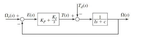
The proportional integral controller of first order plant is as shown below:
Where, the parameter values are as given:
Also, the performance specifications require the time constant of the system to be
The values of gains for the PI controller are as follows:
Case 1. For
Case 2. For
Case 3. For a root separation factor of 10,
Concept Used:
- The transfer functions for the block diagram are as shown below:
- The steady-state error of a system using final value theorem is:
Calculation:
From the block diagram as shown, the transfer functions are as:
Therefore, the response
And from the block diagram shown in figure, we have
On keeping the values of the parameters such that
Case 1. When
Since,
Therefore, for unit-ramp command response
Thus, the steady-state error for this design is:
Therefore, for zero command response
Thus, the steady-state error for this design is:
Case 2. When
Since,
Therefore, for unit-ramp command response
Thus, the steady-state error for this design is:
Therefore, for zero command response
Thus, the steady-state error for this design is:
Case 3. For a root separation factor of 10,
Since,
Therefore, for unit-ramp command response
Thus, the steady-state error for this design is:
Therefore, for zero command response
Thus, the steady-state error for this design is:
Conclusion:
The peak torque values for all the cases are:
Case 1. For
Error due to unit-ramp command:
Error due to unit-ramp disturbance:
Case 2. For
Error due to unit-ramp command:
Error due to unit-ramp disturbance:
Case 3. For a root separation factor of 10,
Error due to unit-ramp command:
Error due to unit-ramp disturbance:
Want to see more full solutions like this?
Chapter 10 Solutions
EBK SYSTEM DYNAMICS


- my ID is 016948724 Last 2 ID# 24 Last 3 ID# 724 please help me to solve this problem step by step show me how to solve first wirte the line actions and then find the forces {fx=, fy=, mz= and for the last step find the support reactions and find forcesarrow_forwardUppgift 1 (9p) 3 m 3 m 3 m 3 m H G F 3 m ↑ Dy D B AAY 30° 8 kN Ay Fackverket i figuren ovan är belastat med en punktlast. Bestäm normalkraften i stängerna BC, BG och FG.arrow_forwardThe cardiovascular countercurrent heat exchnager mechanism is to warm venous blood from 28 degrees C to 35 degrees C at a mass flow rate of 2 g/s. The artery inflow temp is 37 degrees C at a mass flow rate of 5 g/s. The average diameter of the vein is 5 cm and the overall heat transfer coefficient is 125 W/m^2*K. Determine the overall blood vessel length needed too warm the venous blood to 35 degrees C if the specific heat of both arterial and venous blood is constant and equal to 3475 J/kg*K.arrow_forward
- The forces Qy=12 kNQy=12kN and Qz=16 kNQz=16kN act on the profile at the shear center C. Calculate: a) Shear flow at point B (2 points)b) Shear stress at point D (3 points)arrow_forwardConsider the feedback controlled blending system shown below, which is designed to keep theoutlet concentration constant despite potential variations in the stream 1 composition. The density of all streamsis 920 kg/m3. At the nominal steady state, the flow rates of streams 1 and 2 are 950 and 425 kg/min,respectively, the liquid level in the tank is 1.3 m, the incoming mass fractions are x1 = 0.27, x2 = 0.54. Noticethe overflow line, indicating that the liquid level remains constant (i.e. any change in total inlet flow ratetranslates immediately to the same change in the outlet flow rate). You may assume the stream 1 flowrate andthe stream 2 composition are both constant. Use minutes as the time unit throughout this problem. d) Derive the first order process and disturbance transfer functions;Gp= Kp/(tou*s+1) and Gd=Kd/(tou*s+1) and calculate and list the values and units of the parameters. e) Using the given information, write the general forms of Gm, GIP, and Gv below(in terms of…arrow_forwarda) Briefly explain what ratio control is. Give an example of a common chemical engineering situation in whichratio control would be useful and for that example state exactly how ratio control works (what would bemeasured, what is set, and how the controller logic works).b) Briefly explain what cascade control is. Give an example of a common chemical engineering situation inwhich cascade control would be useful and for that example state exactly how cascade control works (whatwould be measured, what is set, and how the controller logic works).arrow_forward
- Determine the reaction force acting on the beam AB, given F = 680 N. 5 4 4 m 3 3 A B 30° 3 m F (N)arrow_forwardThe frame in the figure is made of an HEA 300 profile (E = 210 GPa, material S355).a) Determine the support reactions at point A. (1p)b) Sketch the bending moment diagram caused by the loading. (1p)c) Using the principle of virtual work (unit load method), calculate the vertical displacement at point B using moment diagrams. Also take into account the compression of the column. (3p)arrow_forward9 kN/m 6 kN/m 3 m 6 m Bestäm, med hjälp av friläggning och jämviktsberäkningar, tvärkrafts- och momentdiagram för balken i figuren. Extrempunkter ska anges med både läge och värde.arrow_forward
- B C 3.0 E F G 40 kN [m] 3.0 3.0 3.0 Fackverket belastas med en punktlast i G enligt figuren. Bestäm normalkraften i stängerna BC, BF och EF.arrow_forwardL q=8 kN/m P= 12 kN En stång belastas av en punklast P vid sin ena ände samt av en jämnt utbredd last q längs hela sin längd. Stången har en tvärsnittsarea A = 150 mm² och är tillverkad av stål med elasticitetsmodul E-210 GPa. Stångens längd, i sitt obelastade tillstånd, är Z-3 m. a) Hur stor är den största normalspänning som uppstår i stången? b) Hur stor blir förlängningen av stången, orsakad av lasterna P och q?arrow_forwardA turbocharged engine with a compression ratio of 8 is being designed using an air standard cycle. The ambient air is assumed to be 300K and 100 kPa. The temperature at the end of the compression in the cylinder is desired to be 1000K, assuming no combustion prior to reaching TDC. At the end of the cylinder expansion the temperature is also desired to be 1000K. If both the turbine and the compressor have mechanical efficiencies of 80%, what will be the pressure ratio of the compressor and what will be the turbine exhaust temperature?arrow_forward
 Elements Of ElectromagneticsMechanical EngineeringISBN:9780190698614Author:Sadiku, Matthew N. O.Publisher:Oxford University Press
 Mechanics of Materials (10th Edition)Mechanical EngineeringISBN:9780134319650Author:Russell C. HibbelerPublisher:PEARSON
 Thermodynamics: An Engineering ApproachMechanical EngineeringISBN:9781259822674Author:Yunus A. Cengel Dr., Michael A. BolesPublisher:McGraw-Hill Education
 Control Systems EngineeringMechanical EngineeringISBN:9781118170519Author:Norman S. NisePublisher:WILEY
 Mechanics of Materials (MindTap Course List)Mechanical EngineeringISBN:9781337093347Author:Barry J. Goodno, James M. GerePublisher:Cengage Learning
 Engineering Mechanics: StaticsMechanical EngineeringISBN:9781118807330Author:James L. Meriam, L. G. Kraige, J. N. BoltonPublisher:WILEY