
Videos
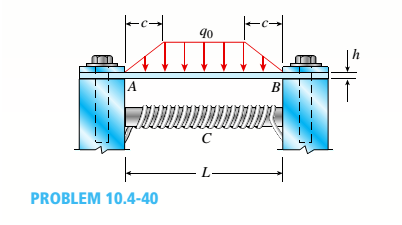
A thin steel beam AB used in conjunction with an electromagnet in a high-energy physics experiment is securely bolted to rigid supports (see figure), A magnetic field produced by coils C results in a force acting on the beam. The force is trapezoidally distributed with maximum intensity q0= 18 kN/m. The length of the beam between supports is L = 200 mm, and the dimension c of the trapezoidal load is 50 mm. The beam has a rectangular cross section with width b = 60 and height h = 20 mm.
Determine the maximum bending stress
The maximum bending stress and the maximum deflection.
Answer to Problem 10.4.40P
The maximum bending stress is
The maximum deflection in the beam is
Explanation of Solution
Given information:
Width of the rectangular cross-section is
The below figure shows the schematic diagram of the beam with parameters.
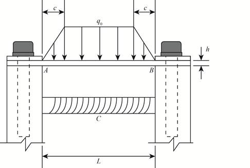
Figure-(1)
Write the expression for the equilibrium in vertical direction.
Substitute
Here, the reaction force at point A is
There is symmetry in the beam therefore the reaction forces at A and B will be same.
There is symmetry in the beam therefore the moment at A will be equal to moment at B .
Write the expression for the relation between the reaction forces at A and B .
Write the expression for the relation between the moment about A and B .
Here, the moment about A is
The below figure shows the deflection in the beam.
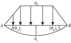
Figure-(2)
Write the expression for the compatibility.
Here, the rotation about point A is
The below figure shows the deflection slope.
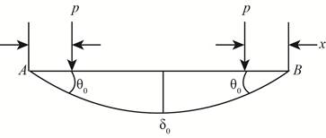
Figure-(3)
Write the expression for the slope from figure-(3).
Here, the load is
Write the expression for the deflection for figure-(3).
Write the expression for load.
Write the expression for load from
Write the expression for load from
Write the expression for rotation about A .
Write the expression for the deflection.
The below figure shows the moments at the ends of the beam.
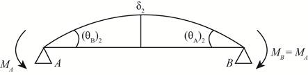
Figure-(4)
Write the expression for the compatibility.
Write the expression for slope for figure-(4).
Write the expression for the deflection for figure-(4).
Write the expression for maximum deflection.
Substitute
Write the expression for the moment about C .
Write the expression for the maximum moment.
Write the expression for moment of inertia.
Here, moment of inertia is
Write the expression for the section modulus.
Write the expression for the normal stress.
Calculation:
Substitute
Substitute
Substitute
Substitute
Substitute
Substitute
Substitute
Substitute
Substitute
Conclusion:
The maximum bending stress is
The maximum deflection in the beam is
Want to see more full solutions like this?
Chapter 10 Solutions
Bundle: Mechanics Of Materials, Loose-leaf Version, 9th + Mindtap Engineering, 2 Terms (12 Months) Printed Access Card


- (Read Question)arrow_forwardIn figure A, the homogeneous rod of constant cross section is attached to unyielding supports. In figure B, a homogeneous bar with a cross-sectional area of 600 mm2 is attached to rigid supports. The bar carries the axial loads P1 = 20 kN and P2 = 60 kN, as shown.1. In figure A, derive the expression that calculates the reaction R1 in terms of P, and the given dimensions.2. In figure B, calculate the reaction (kN) at A.3. In figure B, calculate the maximum axial stress (MPa) in the rod.arrow_forward(Read image)arrow_forward
- (Read Image)arrow_forwardM16x2 grade 8.8 bolts No. 25 C1- Q.2. The figure is a cross section of a grade 25 cast-iron pressure vessel. A total of N, M16x2.0 grade 8.8 bolts are to be used to resist a separating force of 160 kN. (a) Determine ks, km, and C. (b) Find the number of bolts required for a load factor of 2 where the bolts may be reused when the joint 19 mm is taken apart. (c) with the number of bolts obtained in (b), determine the realized load factor for overload, the yielding factor of safety, and the separation factor of safety. 19 mmarrow_forwardProblem4. The thin uniform disk of mass m = 1-kg and radius R = 0.1m spins about the bent shaft OG with the angular speed w2 = 20 rad/s. At the same time, the shaft rotates about the z-axis with the angular speed 001 = 10 rad/s. The angle between the bent portion of the shaft and the z-axis is ẞ = 35°. The mass of the shaft is negligible compared to the mass of the disk. a. Find the angular momentum of the disk with respect to point G, based on the axis orientation as shown. Include an MVD in your solution. b. Find the angular momentum of the disk with respect to point O, based on the axis orientation as shown. (Note: O is NOT the center of fixed-point rotation.) c. Find the kinetic energy of the assembly. z R R 002 2R x Answer: H = -0.046ĵ-0.040 kg-m²/sec Ho=-0.146-0.015 kg-m²/sec T 0.518 N-m =arrow_forward
- Problem 3. The assembly shown consists of a solid sphere of mass m and the uniform slender rod of the same mass, both of which are welded to the shaft. The assembly is rotating with angular velocity w at a particular moment. Find the angular momentum with respect to point O, in terms of the axes shown. Answer: Ñ。 = ½mc²wcosßsinßĵ + (}{mr²w + 2mb²w + ½ mc²wcos²ß) k 3 m r b 2 C لا marrow_forwardOnly question 2arrow_forwardOnly question 1arrow_forward
- Only question 3arrow_forwardI have Euler parameters that describe the orientation of N relative to Q, e = -0.7071*n3, e4 = 0.7071. I have Euler parameters that describe the orientation of U relative to N, e = -1/sqrt(3)*n1, e4 = sqrt(2/3). After using euler parameter rule of successive rotations, I get euler parameters that describe the orientation of U relative to Q, e = -0.4082*n1 - 0.4082*n2 - 0.5774*n3. I need euler parameters that describe the orientation of U relative to Q in vector basis of q instead of n. How do I get that?arrow_forwardDescribe at least 4 processes in engineering where control charts are (or should be) appliedarrow_forward
 Mechanics of Materials (MindTap Course List)Mechanical EngineeringISBN:9781337093347Author:Barry J. Goodno, James M. GerePublisher:Cengage Learning