
Concept explainers
Videos
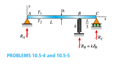
Solve the preceding problem by integrating the differential equation of the deflection curve.
(a)
The reactions for beam at all supports.
Answer to Problem 10.5.5P
The reaction at support
The reaction at support
The reaction at support
Explanation of Solution
Given information:
The two spans of beam are
Write the Expression for force equilibrium in vertical direction.
Here, reaction produced at
Write the expression for moment about point
Here,
Write the expression for moment about point
Here,
Write the expression for double order differential equation for the deflection curve when any value between
Here, double order differential of deflection curve is
Write the expression for single order derivative of deflection curve when any value between
Here, length at which deflection has to be calculate is
Write the expression for deflection curve when any value between
Here, deflection at a point
Write the expression for first boundary condition.
Here, deflection when
Write the expression for second boundary condition when
Here, single order differential of deflection curve from the loads left to spring is
Write the expression for third boundary condition when
Write the expression for fourth boundary condition.
Here, deflection when
Write the expression for differential equation for the deflection curve when any value between
Write the expression for single order derivative of deflection curve when any value between
Write the expression for deflection curve when any value between
Write the expression for compatibility Equation for spring when
Substituted
Substitute
Substitute
Substitute
Substitute
Substitute
Substitute
Substitute
Substitute
Substitute
Substitute
Substitute
Substitute
Solve Equation (XXIII) and Equation (XXIV).
Substitute
Conclusion:
The reaction at support
The reaction at support
The reaction at support
(b)
The reactions at all the supports when value of
Answer to Problem 10.5.5P
The reaction at support
The reaction at support
The reaction at support
Explanation of Solution
Take limit of
Take limit of
Take limit of
Conclusion:
The reaction at support
The reaction ay support
The reaction at support
Want to see more full solutions like this?
Chapter 10 Solutions
Bundle: Mechanics Of Materials, Loose-leaf Version, 9th + Mindtap Engineering, 2 Terms (12 Months) Printed Access Card


- PROBLEM 3.46 The solid cylindrical rod BC of length L = 600 mm is attached to the rigid lever AB of length a = 380 mm and to the support at C. When a 500 N force P is applied at A, design specifications require that the displacement of A not exceed 25 mm when a 500 N force P is applied at A For the material indicated determine the required diameter of the rod. Aluminium: Tall = 65 MPa, G = 27 GPa. Aarrow_forwardFind the equivalent mass of the rocker arm assembly with respect to the x coordinate. k₁ mi m2 k₁arrow_forward2. Figure below shows a U-tube manometer open at both ends and containing a column of liquid mercury of length l and specific weight y. Considering a small displacement x of the manometer meniscus from its equilibrium position (or datum), determine the equivalent spring constant associated with the restoring force. Datum Area, Aarrow_forward
- 1. The consequences of a head-on collision of two automobiles can be studied by considering the impact of the automobile on a barrier, as shown in figure below. Construct a mathematical model (i.e., draw the diagram) by considering the masses of the automobile body, engine, transmission, and suspension and the elasticity of the bumpers, radiator, sheet metal body, driveline, and engine mounts.arrow_forward3.) 15.40 – Collar B moves up at constant velocity vB = 1.5 m/s. Rod AB has length = 1.2 m. The incline is at angle = 25°. Compute an expression for the angular velocity of rod AB, ė and the velocity of end A of the rod (✓✓) as a function of v₂,1,0,0. Then compute numerical answers for ȧ & y_ with 0 = 50°.arrow_forward2.) 15.12 The assembly shown consists of the straight rod ABC which passes through and is welded to the grectangular plate DEFH. The assembly rotates about the axis AC with a constant angular velocity of 9 rad/s. Knowing that the motion when viewed from C is counterclockwise, determine the velocity and acceleration of corner F.arrow_forward
- 500 Q3: The attachment shown in Fig.3 is made of 1040 HR. The static force is 30 kN. Specify the weldment (give the pattern, electrode number, type of weld, length of weld, and leg size). Fig. 3 All dimension in mm 30 kN 100 (10 Marks)arrow_forward(read image) (answer given)arrow_forwardA cylinder and a disk are used as pulleys, as shown in the figure. Using the data given in the figure, if a body of mass m = 3 kg is released from rest after falling a height h 1.5 m, find: a) The velocity of the body. b) The angular velocity of the disk. c) The number of revolutions the cylinder has made. T₁ F Rd = 0.2 m md = 2 kg T T₂1 Rc = 0.4 m mc = 5 kg ☐ m = 3 kgarrow_forward
- (read image) (answer given)arrow_forward11-5. Compute all the dimensional changes for the steel bar when subjected to the loads shown. The proportional limit of the steel is 230 MPa. 265 kN 100 mm 600 kN 25 mm thickness X Z 600 kN 450 mm E=207×103 MPa; μ= 0.25 265 kNarrow_forwardT₁ F Rd = 0.2 m md = 2 kg T₂ Tz1 Rc = 0.4 m mc = 5 kg m = 3 kgarrow_forward
 Mechanics of Materials (MindTap Course List)Mechanical EngineeringISBN:9781337093347Author:Barry J. Goodno, James M. GerePublisher:Cengage Learning