
Engineering Electromagnetics
9th Edition
ISBN: 9781260029963
Author: Hayt
Publisher: MCG
expand_more
expand_more
format_list_bulleted
Concept explainers
Videos
Textbook Question
Chapter 10, Problem 10.42P
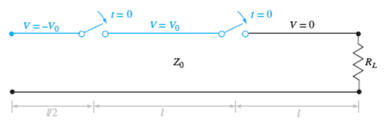
Figure 10.38 See Problem 10.42.
A simple frozen wave generator is shown in Figure 10.38. Both switches are closed simultaneously at t = 0. Construct an appropriate voltage reflection diagram for the case in which RL = Z0. Determine and plot the load resistor voltage as a function of time.
Expert Solution & Answer
Want to see the full answer?
Check out a sample textbook solution
Students have asked these similar questions
If C is the circle |z|=4 evaluate ff(z)dz for each of the following
functions using residue.
Z
(a)f(z) = z²-1
Z+1
1
(b)f(z) =
=
(c)f(z)
=
z²(z+2)
z(z-2)³
z²
1
1
(d) f(z) =
=
(e) f(z) =
(f) f(z) =
(z²+3z+2)²
z²+z+1
z(z²+6z+4)
5. Answer the following questions. Take help from ChatGPT to answer these questions (if
you need). Write the answers briefly using your own words with no more than two sentences,
and check whether ChatGPT is giving you the appropriate answers in the context of our
class.
a) What is the Bode plot? What kind of input do we consider for the frequency-response-
based method?
b) What is the advantage of design using the frequency-response method?
c) Define gain margin, phase margin, gain crossover frequency, and phase crossover
frequency.
Phase (deg)
3. The Bode diagram of a system is shown below.
Magnitude (dB)
System: sys
-10
Frequency (rad/s): 0.141
Magnitude (dB): -15.6
-20
-30
40
-50
-60
0
-45
-90
-135
101
10°
Bode Diagram
System: sys
Frequency (radis): 10
Magnitude (dB): -18.9
System: sys
Frequency (rad/s): 10
Phase (deg):-52.2
101
Frequency (rad/s)
102
103
Find the steady-state output of the system for each of the following inputs.
a) u(t) = 100
b) u(t) 100 cos(10 t + 10°)
=
c) u(t) = 500 + 200 cos(10 t + 10°)
Chapter 10 Solutions
Engineering Electromagnetics
Ch. 10 - The parameters of a certain transmission line...Ch. 10 - A sinusoidal wave on a transmission line is...Ch. 10 - Prob. 10.3PCh. 10 - A sinusoidal voltage V0, frequency , and phase...Ch. 10 - Two voltage waves of equal amplitude V0 and radian...Ch. 10 - A 50 load is attached to a 50-m section of the...Ch. 10 - Prob. 10.7PCh. 10 - An absolute measure of power is the dBm scale, in...Ch. 10 - A 100-m transmission line is used to propagate a...Ch. 10 - Two lossless transmission lines having different...
Ch. 10 - Two voltage waves of equal amplitude V0, which...Ch. 10 - In a circuit in which a sinusoidal voltage source...Ch. 10 - The skin effect mechanism in transmission lines is...Ch. 10 - A lossless transmission line having characteristic...Ch. 10 - Figure 10.29 See Problem 10.15. For the...Ch. 10 - A 100 lossless transmission line is connected to a...Ch. 10 - Determine the average power absorbed by each...Ch. 10 - The line shown in Figure 10.31 is lossless. Find s...Ch. 10 - A lossless transmission line is 50 cm in length...Ch. 10 - (a) Determine s on the transmission line of Figure...Ch. 10 - Prob. 10.21PCh. 10 - Prob. 10.22PCh. 10 - The normalized load on a lossless transmission...Ch. 10 - Prob. 10.24PCh. 10 - Prob. 10.25PCh. 10 - A 75 lossless line is of length 1.2 . It is...Ch. 10 - Prob. 10.27PCh. 10 - The wavelength on a certain lossless line is 10...Ch. 10 - Prob. 10.29PCh. 10 - A two-wire line constructed of lossless wire of...Ch. 10 - In order to compare the relative sharpness of the...Ch. 10 - In Figure 10.17, let ZL=250 and Z0=50. Find the...Ch. 10 - In Figure 10.17, let ZL=100+j150 and Z0=100. Find...Ch. 10 - The lossless line shown in Figure 10.35 is...Ch. 10 - Prob. 10.35PCh. 10 - The two-wire lines shown in Figure 10.36 are all...Ch. 10 - Prob. 10.37PCh. 10 - Repeat Problem 10.37, with, Z0=50 and RL=Rg=25....Ch. 10 - In the transmission line of Figure 10.20, Z0=50,...Ch. 10 - In the charged line of Figure 10.25, the...Ch. 10 - In the transmission line of Figure 10.37, the...Ch. 10 - Figure 10.38 See Problem 10.42. A simple frozen...Ch. 10 - Figure 10.39 See Problem 10.43. In Figure 10.39,...
Knowledge Booster


Learn more about
Need a deep-dive on the concept behind this application? Look no further. Learn more about this topic, electrical-engineering and related others by exploring similar questions and additional content below.Similar questions
- Phase (deg) 270 4. Consider a closed-loop system with unity (negative) feedback. The Bode diagram of the open-loop transfer function is given below. Magnitude (dB) -500 -150 -50 10 dB System Frequency (eds): 6.63 Magnitude (B) 0.0778 Буку Frequency(): 10.1 Magnitude ()-705 Frequency(6.63 Phase (deg): -144 Frequency (rad): 10.1 Phase (deg): -180 101 Frequency (rad) a) Find the gain margin, phase margin, gain crossover frequency, and phase crossover frequency. b) Is the closed-loop system stable? What is the steady-state error for step-input?arrow_forwardelectric plantsarrow_forwardsolve and show workarrow_forward
- z+4 What is the value of cz²+2z+5 dz a) If C is the circle |z|=1. c) If C is the circle |z+1+i|=2. b) If C is the circle |z+1-i|=2.arrow_forwardApplication of Complex Inversion Integral for Inverse Z-transform Find Z-1 (z-1)(z-2) }arrow_forwardz+4 What is the value of cz²+2z+5 a) If C is the circle |z|=1. dz b) If C is the circle |z+1-i|=2. c) If C is the circle |z+1+i|=2.arrow_forward
- z+4 What is the value of √cz²+2z+5 dz Sc a) If C is the circle |z|=1. c) If C is the circle |z+1+i|=2. b) If C is the circle |z+1-i|=2.arrow_forwardz+1 What is the value of Sc 73. C -2z² 3-zzz dz i) ii) iii) If C is the circle |z|=1. If C is the circle |z-2-i|=2. If C is the circle |z-1-2i|=2.arrow_forwardApplication of Complex Inversion Integral for Inverse Z-transform Find Z-1 {(2-1)(2+2)}arrow_forward
- 4z Find the residue of f(z) = (z-3)(z+1)²arrow_forwardwhat is the integral of f(z): -3z+4 = around the circle z(z-1)(z-2) |z|=3/2?arrow_forward1. The communication channel bandwidth uses is 25 MHz centered at 1GHz and uses BPSK. The noise power spectral density of the channel is 10^-9 W/Hz. The channel loss between the transmitter and receiver is 25dB. The application requires a BER of less than 10^-4. Determine the minimum transmit power required.arrow_forward
arrow_back_ios
SEE MORE QUESTIONS
arrow_forward_ios
Recommended textbooks for you
 Power System Analysis and Design (MindTap Course ...Electrical EngineeringISBN:9781305632134Author:J. Duncan Glover, Thomas Overbye, Mulukutla S. SarmaPublisher:Cengage Learning
Power System Analysis and Design (MindTap Course ...
Electrical Engineering
ISBN:9781305632134
Author:J. Duncan Glover, Thomas Overbye, Mulukutla S. Sarma
Publisher:Cengage Learning
How does an Antenna work? | ICT #4; Author: Lesics;https://www.youtube.com/watch?v=ZaXm6wau-jc;License: Standard Youtube License