
Vector Mechanics for Engineers: Statics
12th Edition
ISBN: 9781259977268
Author: Ferdinand P. Beer, E. Russell Johnston Jr., David Mazurek
Publisher: McGraw-Hill Education
expand_more
expand_more
format_list_bulleted
Videos
Textbook Question
Chapter 10, Problem 10.104RP
Derive an expression for the magnitude of the force Q required to maintain the equilibrium of the mechanism shown.
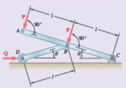
Fig. P10.104
Expert Solution & Answer
Want to see the full answer?
Check out a sample textbook solution
Students have asked these similar questions
I really don't know how to approach this problem i've tried approaching it with some of the torsional stress equations I know but i'm comming up with awnsers that don't make any sence can you please help me with this?
I tried this problem and don't know what I did wrong or how else I could approach it can you please help me out?
Q3: An engine produce 750 kW power and uses gaseous C12H26 as a fuel
at 25 C; 200% theoretical air is used and air enters at 500 K. The products
of combustion leave at 800 K. The heat loss from the engine is 175 kW.
Determine the fuel consumption for complete combustion.
Chapter 10 Solutions
Vector Mechanics for Engineers: Statics
Ch. 10.1 - Determine the vertical force P that must be...Ch. 10.1 - Determine the horizontal force P that must be...Ch. 10.1 - Prob. 10.3PCh. 10.1 - 10.3 and 10.4 Determine the couple M that must be...Ch. 10.1 - A spring of constant 15 kN/m connects points C and...Ch. 10.1 - A spring of constant 15 kN/m connects points C and...Ch. 10.1 - The two-bar linkage shown is supported by a pin...Ch. 10.1 - Determine the weight W that balances the 10-lb...Ch. 10.1 - Prob. 10.9PCh. 10.1 - Prob. 10.10P
Ch. 10.1 - Prob. 10.11PCh. 10.1 - Knowing that the line of action of the force Q...Ch. 10.1 - Solve Prob. 10.12 assuming that the force P...Ch. 10.1 - The mechanism shown is acted upon by the force P....Ch. 10.1 - Prob. 10.15PCh. 10.1 - 10.15 and 10.16 Derive an expression for the...Ch. 10.1 - A uniform rod AB with length l and weight W is...Ch. 10.1 - The pin at C is attached to member BCD and can...Ch. 10.1 - For the linkage shown, determine the couple M...Ch. 10.1 - For the linkage shown, determine the force...Ch. 10.1 - A 4-kN force P is applied as shown to the piston...Ch. 10.1 - A couple M with a magnitude of 100 Nm isapplied as...Ch. 10.1 - Rod AB is attached to a block at A that can...Ch. 10.1 - Solve Prob. 10.23, assuming that the 800-N force...Ch. 10.1 - Prob. 10.25PCh. 10.1 - Determine the value of corresponding to...Ch. 10.1 - Prob. 10.27PCh. 10.1 - Determine the value of corresponding to...Ch. 10.1 - Prob. 10.29PCh. 10.1 - Two rods AC and CE are connected by a pin at Cand...Ch. 10.1 - Solve Prob. 10.30 assuming that force P is movedto...Ch. 10.1 - Two bars AD and DG are connected by a pin at Dand...Ch. 10.1 - Solve Prob. 10.32 assuming that the 900-N...Ch. 10.1 - Two 5-kg bars AB and BC are connected by a pin atB...Ch. 10.1 - A vertical force P with a magnitude of 150 N...Ch. 10.1 - Prob. 10.36PCh. 10.1 - 10.37 and 10.38 Knowing that the constant of...Ch. 10.1 - Prob. 10.38PCh. 10.1 - The lever AB is attached to the horizontal shaft...Ch. 10.1 - Solve Prob. 10.39, assuming that P = 350 N, l =250...Ch. 10.1 - Prob. 10.41PCh. 10.1 - The position of boom ABC is controlled by...Ch. 10.1 - The position of member ABC is controlled by the...Ch. 10.1 - The position of member ABC is controlled by...Ch. 10.1 - The telescoping arm ABC is used to provide...Ch. 10.1 - Solve Prob. 10.45, assuming that the workers...Ch. 10.1 - Denoting the coefficient of static friction...Ch. 10.1 - Knowing that the coefficient of static...Ch. 10.1 - A block with weight W is pulled up a plane forming...Ch. 10.1 - Derive an expression for the mechanical...Ch. 10.1 - Denoting the coefficient of static friction...Ch. 10.1 - Knowing that the coefficient of static...Ch. 10.1 - Using the method of virtual work,...Ch. 10.1 - Using the method of virtual work, determine...Ch. 10.1 - Referring to Prob. 10.43 and using the value...Ch. 10.1 - Prob. 10.56PCh. 10.1 - Prob. 10.57PCh. 10.1 - Prob. 10.58PCh. 10.2 - Using the method of Sec. 10.2C, solve Prob. 10.29....Ch. 10.2 - Using the method of Sec. 10.2C, solve Prob. 10.30....Ch. 10.2 - Using the method of Sec. 10.2C, solve Prob. 10.31....Ch. 10.2 - Using the method of Sec. 10.2C, solve Prob. 10.32....Ch. 10.2 - Using the method of Sec. 10.2C, solve Prob. 10.34....Ch. 10.2 - Prob. 10.64PCh. 10.2 - Using the method of Sec. 10.2C, solve Prob. 10.37....Ch. 10.2 - Prob. 10.66PCh. 10.2 - Prob. 10.67PCh. 10.2 - Show that equilibrium is neutral in Prob. 10.7....Ch. 10.2 - Two uniform rods, each with a mass m, areattached...Ch. 10.2 - Two uniform rods, AB and CD, are attached to gears...Ch. 10.2 - Two uniform rods AB and CD, of the same length...Ch. 10.2 - Two uniform rods, each of mass m and length l, are...Ch. 10.2 - Using the method of Sec. 10.2C, solve Prob....Ch. 10.2 - In Prob. 10.40, determine whether each of...Ch. 10.2 - A load W of magnitude 144 lb is applied to...Ch. 10.2 - Prob. 10.76PCh. 10.2 - Prob. 10.77PCh. 10.2 - Prob. 10.78PCh. 10.2 - A slender rod AB with a weight W is attached to...Ch. 10.2 - A slender rod AB with a weight W is attached totwo...Ch. 10.2 - Prob. 10.81PCh. 10.2 - A spring AB of constant k is attached to two...Ch. 10.2 - A slender rod AB is attached to two collars A and...Ch. 10.2 - Prob. 10.84PCh. 10.2 - 10.85 and 10.86 Cart B, which weighs 75 kN, rolls...Ch. 10.2 - 10.85 and 10.86 Cart B, which weighs 75 kN, rolls...Ch. 10.2 - 10.87 and 10.88 Collar A can slide freely on the...Ch. 10.2 - 10.87 and 10.88 Collar A can slide freely on the...Ch. 10.2 - Prob. 10.89PCh. 10.2 - A vertical bar AD is attached to two springs...Ch. 10.2 - Rod AB is attached to a hinge at A and to two...Ch. 10.2 - Rod AB is attached to a hinge at A and to...Ch. 10.2 - Two bars are attached to a single spring of...Ch. 10.2 - Prob. 10.94PCh. 10.2 - The horizontal bar BEH is connected to three...Ch. 10.2 - The horizontal bar BEH is connected to three...Ch. 10.2 - Bars AB and BC, each with a length l and of...Ch. 10.2 - Prob. 10.98PCh. 10.2 - Prob. 10.99PCh. 10.2 - Prob. 10.100PCh. 10 - Determine the vertical force P that must be...Ch. 10 - Determine the couple M that must be applied...Ch. 10 - Determine the force P required to maintain...Ch. 10 - Derive an expression for the magnitude of the...Ch. 10 - Derive an expression for the magnitude of the...Ch. 10 - A vertical load W is applied to the linkage at B....Ch. 10 - A force P with a magnitude of 240 N is applied to...Ch. 10 - Two identical rods ABC and DBE are connected bya...Ch. 10 - Solve Prob. 10.108 assuming that the 24-lb load...Ch. 10 - Two uniform rods each with a mass m and length...Ch. 10 - A homogeneous hemisphere with a radius r isplaced...Ch. 10 - A homogeneous hemisphere with a radius r isplaced...
Knowledge Booster


Learn more about
Need a deep-dive on the concept behind this application? Look no further. Learn more about this topic, mechanical-engineering and related others by exploring similar questions and additional content below.Similar questions
- Qu 5 Determine the carburizing time necessary to achieve a carbon concentration of 0.30 wt% at a position 4 mm into an iron carbon alloy that initially contains 0.10 wt% C. The surface concentration is to be maintained at 0.90 wt% C, and the treatment is to be conducted at 1100°C. Use the data for the diffusion of carbon into y-iron: Do = 2.3 x10⁻⁵ m2/s and Qd = 148,000 J/mol. Express your answer in hours to three significant figures. show all work step by step problems formula material sciencearrow_forward(Read Question)arrow_forwardIn figure A, the homogeneous rod of constant cross section is attached to unyielding supports. In figure B, a homogeneous bar with a cross-sectional area of 600 mm2 is attached to rigid supports. The bar carries the axial loads P1 = 20 kN and P2 = 60 kN, as shown.1. In figure A, derive the expression that calculates the reaction R1 in terms of P, and the given dimensions.2. In figure B, calculate the reaction (kN) at A.3. In figure B, calculate the maximum axial stress (MPa) in the rod.arrow_forward
- (Read image)arrow_forward(Read Image)arrow_forwardM16x2 grade 8.8 bolts No. 25 C1- Q.2. The figure is a cross section of a grade 25 cast-iron pressure vessel. A total of N, M16x2.0 grade 8.8 bolts are to be used to resist a separating force of 160 kN. (a) Determine ks, km, and C. (b) Find the number of bolts required for a load factor of 2 where the bolts may be reused when the joint 19 mm is taken apart. (c) with the number of bolts obtained in (b), determine the realized load factor for overload, the yielding factor of safety, and the separation factor of safety. 19 mmarrow_forward
- Problem4. The thin uniform disk of mass m = 1-kg and radius R = 0.1m spins about the bent shaft OG with the angular speed w2 = 20 rad/s. At the same time, the shaft rotates about the z-axis with the angular speed 001 = 10 rad/s. The angle between the bent portion of the shaft and the z-axis is ẞ = 35°. The mass of the shaft is negligible compared to the mass of the disk. a. Find the angular momentum of the disk with respect to point G, based on the axis orientation as shown. Include an MVD in your solution. b. Find the angular momentum of the disk with respect to point O, based on the axis orientation as shown. (Note: O is NOT the center of fixed-point rotation.) c. Find the kinetic energy of the assembly. z R R 002 2R x Answer: H = -0.046ĵ-0.040 kg-m²/sec Ho=-0.146-0.015 kg-m²/sec T 0.518 N-m =arrow_forwardProblem 3. The assembly shown consists of a solid sphere of mass m and the uniform slender rod of the same mass, both of which are welded to the shaft. The assembly is rotating with angular velocity w at a particular moment. Find the angular momentum with respect to point O, in terms of the axes shown. Answer: Ñ。 = ½mc²wcosßsinßĵ + (}{mr²w + 2mb²w + ½ mc²wcos²ß) k 3 m r b 2 C لا marrow_forwardOnly question 2arrow_forward
- Only question 1arrow_forwardOnly question 3arrow_forwardI have Euler parameters that describe the orientation of N relative to Q, e = -0.7071*n3, e4 = 0.7071. I have Euler parameters that describe the orientation of U relative to N, e = -1/sqrt(3)*n1, e4 = sqrt(2/3). After using euler parameter rule of successive rotations, I get euler parameters that describe the orientation of U relative to Q, e = -0.4082*n1 - 0.4082*n2 - 0.5774*n3. I need euler parameters that describe the orientation of U relative to Q in vector basis of q instead of n. How do I get that?arrow_forward
arrow_back_ios
SEE MORE QUESTIONS
arrow_forward_ios
Recommended textbooks for you
 International Edition---engineering Mechanics: St...Mechanical EngineeringISBN:9781305501607Author:Andrew Pytel And Jaan KiusalaasPublisher:CENGAGE L
International Edition---engineering Mechanics: St...
Mechanical Engineering
ISBN:9781305501607
Author:Andrew Pytel And Jaan Kiusalaas
Publisher:CENGAGE L
How to balance a see saw using moments example problem; Author: Engineer4Free;https://www.youtube.com/watch?v=d7tX37j-iHU;License: Standard Youtube License