Videos
Radioactive wastes are packed in a long, thin-walledcylindrical container. The wastes generate thermal energynonuniformly according to the relation
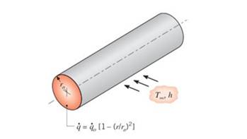
Obtain an expression for the total rate at which energyis generated in a unit length of the container. Use this result to obtain an expression the temperature
Want to see the full answer?
Check out a sample textbook solution
Chapter 1 Solutions
Fundamentals of Heat and Mass Transfer


- number 1 A food product containing 75% moisture content is being frozen. Estimate the specific heat of the product at -10° C when 85% of the water is frozen. The specific heat of the dry product is 2 kJ / (kg ° C). It is assumed that the specific heat of water at -10 ° C is the same as the specific heat of water at 0 ° C, and that the specific heat of ice follows the function Cp es = 0.0062 T Frozen + 2.0649. Cp of frozen product = kJ / kg ° C.arrow_forwardnumber 1 A food product containing 82% moisture content is being frozen. Estimate the specific heat of the product at -8 ° C when 82% of the water is frozen. The specific heat of the dry product is 2.5 kJ / (kg ° C). It is assumed that the specific heat of water at -10 ° C is the same as the specific heat of water at 0 ° C, and that the specific heat of ice follows the function Cp es = 0.0062 T Frozen + 2.0649. Cp of frozen product = kJ / kg ° C.arrow_forwardAn open system is often referred to as control volume, which is a properly selected region in space in which mass and energy can flow across the boundaries as figure 1.2. The boundary of a open thermodynamic system is called the control surface Across the Boundaries E = Yes F 0 = Yes w =Yes Control surface ass YES W CONTROL VOLUME energy YES Figure 1.2. A cooling/heating radiator is an example of such a system – give two more examples of such a system.arrow_forward
- a. True/False Given 1-D steady-state conduction through a wall with uniform heat generation, the heat transfer (Q. W) is constant throughout the wall. TRUE FALSE b. True/False Consider convection heat transfer acting on an object that is in contact with a fluid at temperature T-. Ifh (the convection coefficient) gets very large. it tends to drive the surface temperature of that object to the fluid temperature T-. TRUE FALSE c. Short answer You need to calculate the temperature at the free end (tip) of a long fin. The boundary condītion you should NOT use is: Circle one! Convective tip Adiabatic tip Infinite finarrow_forwardSuppose that we have a wire (or a thin metal rod) of length that is insulated except at the endpoints. Let L denote the position along the wire and let t denote time. The 1- D heat equation is * temperature u 3 insulation O (a^2 u)/(at^2)=c^2 (a^2 u)/(ax^2) (a^2 u)/(at^2 )=c^2 du/əx au/Ət=c^2 (a^2 u)/(ðx^2 ) au/at=c^2 au/Əx nonearrow_forwardEquations of Polytropic Process Definition, diagrams, equations, & sample problems Test Your Skills 14.1 1. A substance undergoes a process such that pV13 = C. If during this process the volume increases by 25% and the initial temperature is 300 K, find the final temperature in K. Your answer Submit Previous activity Jumn to 合曲 60000arrow_forward
- In an electrical discharge machining process, the breakdown voltage across inter electrode gap (IEG) is 200 V and the capacitance of the RC circuit is 50 uF. The energy (in J) released per spark across the IEG is 1arrow_forwardYou witness an industrial fire in which an unknown liquid spilled in to a 8.2 feet diameter circular dike. You were told the tank holding the liquid spilled its entire content of 3,180 kg in to the dike. The fire started and burned for 30 minutes before consuming all the fuel. If the fire had a heat release rate of 50.5 MW what is the chemical heat of combustion of the fuel?arrow_forward3. A metallic rod 20 cm long is heated to a uniform temperature of 100° C. At t = 0 the ends of the bar are plunged into an ice bath at 0° C and thereafter maintained at this temperature. Find an expression for the temperature u(x, t) if the bar is made of cast iron. Material a (cm²/s) Silver 1.71 Copper 1.14 Aluminum 0.86 Cast iron 0.12 Granite 0.011 Brick 0.0038 Water 0.00144 Table 1: Thermal Diffusivity Constants for Common Materialsarrow_forward
- A solar energy storage compartment contains 1,778 rocks that can approximate 3-inch-diameter spheres. The properties of the rocks are k = 2.2 Btu / h ∙ ft ∙ ºF, α = 0.07 ft2 / h, cp = 0.2 Btu / lbm ° F, and the density is 160 lbm / ft3. How long (in hours) would it take for solar energy to saturate the compartment using 200 ° F air from a solar collector? How much energy (in Btu) is stored in the compartment under these conditions if it is initially at 79 ° F and h = 5 Btu / h ∙ ft2 ∙ ºF?arrow_forwardUsing specific heat value at the average temperature, the internal energy (u) change of hydrogen, in kJ/kg, when it is heated from 300 to 600 K is Select one: 4110 6110 O 3249 3113arrow_forward1. In general, the internal energy U depends on both temperature and volume, U=U(TV). The volume dependence comes from the potential energy due to the interactions among the particles. For free particles, there are no interactions, thus, the internal energy U should be independent of the volume, i.e., = 0. Verify this result for ideal gas pV = RT. au avarrow_forward
 Principles of Heat Transfer (Activate Learning wi...Mechanical EngineeringISBN:9781305387102Author:Kreith, Frank; Manglik, Raj M.Publisher:Cengage Learning