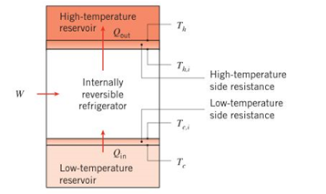
An internally reversible refrigerator has a modifiedcoefficient of performance accounting for realistic heattransfer processes of C O P m = q m W ˙ = q i n q o u t − q i n = R c , i T n , i − T c , i where q i n ¡s the refrigerator cooling rate, q o u t is the heatrejection rate, and W is the power input. Show that C O P m ,can be expressed in terms of the reservoir temperatures T c and T h , the cold and hot thermal resistances R t , c and R t , h , and q i n , as C O P m = T c − q i n R t o t T h − T c + q i n R t o t where R t o t = R t , c + R t , h . Also, show that the power inputmay be expressed as W ˙ = q i n T h − T c + q i n R t o t T c − q i n R t o t
An internally reversible refrigerator has a modifiedcoefficient of performance accounting for realistic heattransfer processes of C O P m = q m W ˙ = q i n q o u t − q i n = R c , i T n , i − T c , i where q i n ¡s the refrigerator cooling rate, q o u t is the heatrejection rate, and W is the power input. Show that C O P m ,can be expressed in terms of the reservoir temperatures T c and T h , the cold and hot thermal resistances R t , c and R t , h , and q i n , as C O P m = T c − q i n R t o t T h − T c + q i n R t o t where R t o t = R t , c + R t , h . Also, show that the power inputmay be expressed as W ˙ = q i n T h − T c + q i n R t o t T c − q i n R t o t
An internally reversible refrigerator has a modifiedcoefficient of performance accounting for realistic heattransfer processes of
C
O
P
m
=
q
m
W
˙
=
q
i
n
q
o
u
t
−
q
i
n
=
R
c
,
i
T
n
,
i
−
T
c
,
i
where
q
i
n
¡s the refrigerator cooling rate,
q
o
u
t
is the heatrejection rate, and W is the power input. Show that
C
O
P
m
,can be expressed in terms of the reservoir temperatures
T
c
and
T
h
, the cold and hot thermal resistances
R
t
,
c
and
R
t
,
h
, and
q
i
n
, as
C
O
P
m
=
T
c
−
q
i
n
R
t
o
t
T
h
−
T
c
+
q
i
n
R
t
o
t
where
R
t
o
t
=
R
t
,
c
+
R
t
,
h
. Also, show that the power inputmay be expressed as
W
˙
=
q
i
n
T
h
−
T
c
+
q
i
n
R
t
o
t
T
c
−
q
i
n
R
t
o
t
The gears shown in the figure have a diametral pitch of 2 teeth per inch and a 20° pressure angle.
The pinion rotates at 1800 rev/min clockwise and transmits 200 hp through the idler pair to gear
5 on shaft c. What forces do gears 3 and 4 transmit to the idler shaft?
TS
I
y
18T
32T
This
a
12
x
18T
C
48T
5
Question 1. Draw 3 teeth for the following pinion and gear respectively. The teeth
should be drawn near the pressure line so that the teeth from the pinion should
mesh those of the gear. Drawing scale (1:1). Either a precise hand drawing or
CAD drawing is acceptable. Draw all the trajectories of the involute lines and the
circles.
Specification: 18tooth pinion and 30tooth gear. Diameter pitch=P=6 teeth /inch.
Pressure angle:20°, 1/P for addendum (a) and 1.25/P for dedendum (b). For fillet,
c=b-a.
5. The figure shows a gear train. There is no friction at the bearings except for the gear tooth forces.
The material of the milled gears is steel having a Brinell hardness of 170. The input shaft speed (n2)
is 800 rpm. The face width and the contact angle for all gears are 1 in and 20° respectively. In this
gear set, the endurance limit (Se) is 15 kpsi and nd (design factor) is 2.
(a) Find the revolution speed of gear 5.
(b) Determine whether each gear satisfies the design factor of 2.0 for bending fatigue.
(c) Determine whether each gear satisfies the design factor of 2.0 for surface fatigue (contact stress).
(d) According to the computation results of the questions (b) and (c), explain the possible failure
mechanisms for each gear.
N4=28
800rpm
N₁=43
N5=34
N₂=14
P(diameteral pitch)=8 for all gears
Coupled to 2.5hp motor
Need a deep-dive on the concept behind this application? Look no further. Learn more about this topic, mechanical-engineering and related others by exploring similar questions and additional content below.


 Refrigeration and Air Conditioning Technology (Mi...Mechanical EngineeringISBN:9781305578296Author:John Tomczyk, Eugene Silberstein, Bill Whitman, Bill JohnsonPublisher:Cengage Learning