
Concept explainers
Videos
The beam AB is pin supported at A and supported by a cable BC. A separate cable CG is used to hold up the frame. If AB weighs 120 lb/ft and the column FC has a weight of 180 lb/ft, determine the resultant internal loadings acting on cross sections located at points D and E.
Answer to Problem 1.1RP
The resultant internal loadings at cross section at D are
The resultant internal loadings at cross section at E are
Explanation of Solution
Given information:
The beam AB is pin supported at A and supported by a cable BC.
The weight of the beam AB is
The weight of the column FC is
Calculation:
Find the loading at the center of the beam AB
Substitute
Convert the unit from lb to kip.
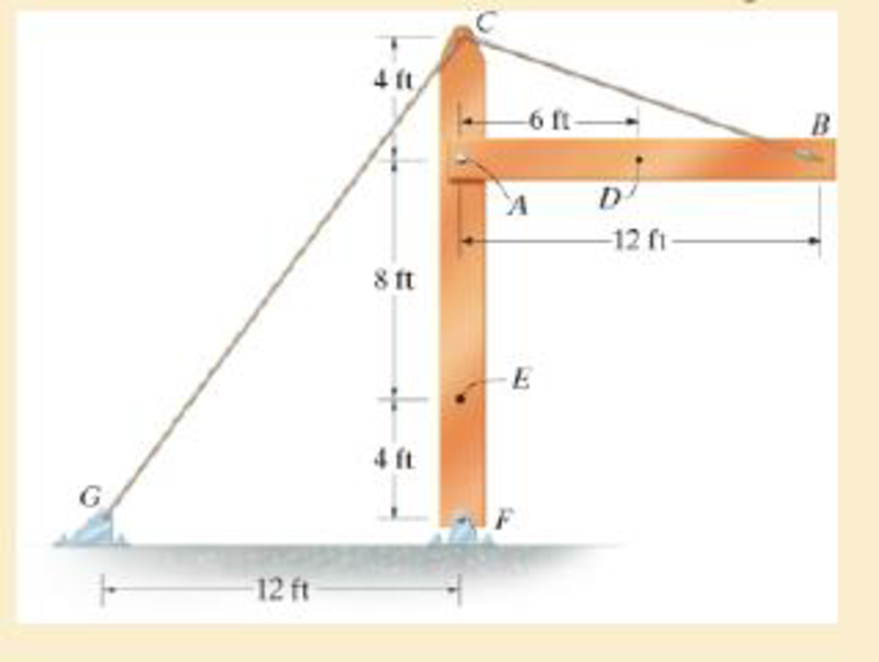
Sketch the Free Body Diagram of the beam AB shown in Figure 1.
Refer to Figure 1.
Find the angle of cable BC to the horizontal
Find the tension in cable BC as shown below.
Take moment about A is Equal to zero.
Find the support reaction at A as shown below.
Apply the Equations of Equilibrium as shown below.
Summation of forces along horizontal direction is Equal to zero.
Summation of forces along vertical direction is Equal to zero.
Find the loading at the center of the beam AD
Substitute
Convert the unit from lb to kip.
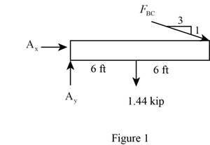
Sketch the Free Body Diagram of the section for point D as shown in Figure 2.
Refer to Figure 2.
Find the internal loadings as shown below.
Apply the Equations of Equilibrium as shown below.
Summation of forces along horizontal direction is Equal to zero.
Summation of forces along vertical direction is Equal to zero.
Take moment about D is Equal to zero.
Hence, the resultant internal loadings at cross section at D are
Find the loading at the center of the column FC
Substitute
Convert the unit from lb to kip.
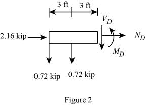
Sketch the Free Body Diagram of the beam FC shown in Figure 3.
Refer to Figure 3.
Find the angle of cable CG to the horizontal.
Find the tension in cable CG as shown below.
Summation of forces along horizontal direction is Equal to zero.
Find the loading at the center of the column FE
Substitute
Convert the unit from lb to kip.
Sketch the Free Body Diagram of the section for point E as shown in Figure 4.
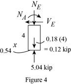
Refer to Figure 4.
Find the internal loadings as shown below.
Apply the Equations of Equilibrium as shown below.
Summation of forces along horizontal direction is Equal to zero.
Summation of forces along vertical direction is Equal to zero.
Take moment about E is Equal to zero.
Therefore, the resultant internal loadings at cross section at E are
Want to see more full solutions like this?
Chapter 1 Solutions
Mechanics of Materials (10th Edition)
Additional Engineering Textbook Solutions
Starting Out with Java: From Control Structures through Objects (7th Edition) (What's New in Computer Science)
Degarmo's Materials And Processes In Manufacturing
Starting Out with C++: Early Objects (9th Edition)
Computer Science: An Overview (13th Edition) (What's New in Computer Science)
Introduction To Programming Using Visual Basic (11th Edition)
Starting Out with Python (4th Edition)


- Find temperatures STRICTLY USING RITZ APPROXIMATION METHODarrow_forwardSolve this Problem using RITZ APPROXIMATION. STEP BY STEParrow_forwardB/40 The body is constructed of a uniform square plate, a uniform straight rod, a uniform quarter‐circular rod, and a particle (negligible dimensions). If each part has the indicated mass, determine the mass moments of inertia of the body about the x‐, y‐, and z‐axes. Answer Given.arrow_forward
- (read image) Answer:arrow_forward(read image) Answer Givenarrow_forwardB/16. The plane area shown in the top portion of the figure is rotated 180° about the x‐axis to form the body of revolution of mass m shown in the lower portion of the figure. Determine the mass moment of inertia of the body about the x‐axis. Answer Givenarrow_forward
- (read image) Answer:arrow_forward(read image) Answer:arrow_forward2nd Law of Thermodynamics A 1.5-ft3 rigid tank contains saturated refrigerant-134 at 170 psia. Initially, 20 percent of the volume isoccupied by liquid and the rest by vapor. A valve at the top of the tank is now opened, and vapor is allowedto escape slowly from the tank. Heat is transferred to the refrigerant such that the pressure inside the tankremains constant. The valve is closed when the last drop of liquid in the tank is vaporized. Determine thetotal heat transfer for this process.arrow_forward
- Draw the shear and bending-moment diagrams for the beam and loading shown, and determine the maximum normal stress due to bending. 4.8 kips/ft 32 kips B C D E I Hinge 8 ft. 2 ft 5 ft 5 ft W12 x 40arrow_forward2nd Law of Thermodynamics A rigid, insulated tank that is initially evacuated is connected through a valve to the supply line that carrieshelium at 300 kPa and 140◦C. Now the valve is opened, and helium is allowed to flow into the tank until thepressure reaches 300 kPa, at which point the valve is closed. Determine the flow work of the helium in thesupply line and the final temperature of the helium in the tank.arrow_forwardDraw the shear and bending-moment diagrams for the beam and loading shown, and determine the maximum normal stress due to bending. 5 kips 10 kips B I W14 x 22 -5 ft -8 ft 5 ft-arrow_forward
 Elements Of ElectromagneticsMechanical EngineeringISBN:9780190698614Author:Sadiku, Matthew N. O.Publisher:Oxford University Press
 Mechanics of Materials (10th Edition)Mechanical EngineeringISBN:9780134319650Author:Russell C. HibbelerPublisher:PEARSON
 Thermodynamics: An Engineering ApproachMechanical EngineeringISBN:9781259822674Author:Yunus A. Cengel Dr., Michael A. BolesPublisher:McGraw-Hill Education
 Control Systems EngineeringMechanical EngineeringISBN:9781118170519Author:Norman S. NisePublisher:WILEY
 Mechanics of Materials (MindTap Course List)Mechanical EngineeringISBN:9781337093347Author:Barry J. Goodno, James M. GerePublisher:Cengage Learning
 Engineering Mechanics: StaticsMechanical EngineeringISBN:9781118807330Author:James L. Meriam, L. G. Kraige, J. N. BoltonPublisher:WILEY