VBE 0.7 V Re www Rc 2 25 20 15 10 5 Vcc +11+ Ves - IsRs - VBE = 0 Rc 1k VBB - VBE = la Ra Base-bias Silicon small signal transistors typically have a ß in the range of 100-300. Complete the following table of values. Beta Vcc= VBB 100 150 200 250 300 1.2k 900 750 500 VBB - VBE RB E = (B + 1) | B = BlB Vaa - VBE RB/B le = RB 1k 500 300 450 250 (KVL) (IE base-bias) Ів IE
VBE 0.7 V Re www Rc 2 25 20 15 10 5 Vcc +11+ Ves - IsRs - VBE = 0 Rc 1k VBB - VBE = la Ra Base-bias Silicon small signal transistors typically have a ß in the range of 100-300. Complete the following table of values. Beta Vcc= VBB 100 150 200 250 300 1.2k 900 750 500 VBB - VBE RB E = (B + 1) | B = BlB Vaa - VBE RB/B le = RB 1k 500 300 450 250 (KVL) (IE base-bias) Ів IE
Introductory Circuit Analysis (13th Edition)
13th Edition
ISBN:9780133923605
Author:Robert L. Boylestad
Publisher:Robert L. Boylestad
Chapter1: Introduction
Section: Chapter Questions
Problem 1P: Visit your local library (at school or home) and describe the extent to which it provides literature...
Related questions
Question
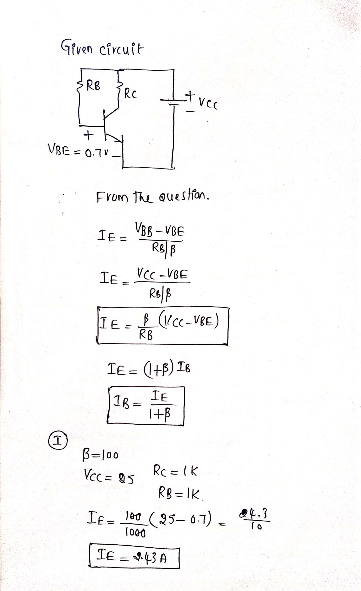
Solve IB and IE

Transcribed Image Text:VBE =
0.7 V
Ro Rc
Vcc = VBB
25
20
15
10
Vcc
5
Ves - IsRs - VBE = 0
VBB
Base-bias
Silicon small signal transistors typically have a ß in the range of 100-300.
Complete the following table of values.
Beta
100
150
200
250
300
Rc
1k
1.2k
900
750
500
B = 100
=
R₁ =
B = 100
1 =
VBE BRB
Example Calculations:
Assuming that we have a ß-100 transistor, what value of the base-bias resistor is required to
yield an emitter current of 1mA? Solving the IE base-bias equation for RB and substituting B, VBB,
VBE, and IE yield 930kn. The closest standard value is 910kn.
B = 300
Vn-V₁
/B
Vra-Ver
R/B
=
VBB - VBE
RB
E = (B + 1) B = BlB
VBB - VBE
RB/B
V₁ = 10V c = = 1mA
RB
1k
500
300
450
250
=
What is the emitter current with a 910k resistor? What is the emitter current if we randomly get
a ß-300 transistor?
10-0.7
910k/300
10-0.7
1mA/100
= 930k
Vi= 10V R₁ = 910k VHF = 0 7V
10 -0.7
910k/100
(KVL)
(IE base-bias)
= 102mA
= 307mA
IB
The emitter current is little changed in using the standard value 910k2 resistor. However, with a
change in ß from 100 to 300, the emitter current has tripled. This is not acceptable in a power
amplifier if we expect the collector voltage to swing from near VCC to near ground. However, for
low level signals from micro-volts to about a volt. the bias point can be centered for a ß of the
square root of (100-300)=173. The bias point will still drift by a considerable amount. However.
low-level signals will not be clipped.
Base-bias is not suitable for high emitter currents, as used in power amplifiers. The base-biased
emitter current is not temperature stable.
Thermal runaway is the result of high emitter current causing a temperature increase which
causes an increase in emitter current, which further increases temperature.
IE
Expert Solution
Step 1

Step by step
Solved in 3 steps with 3 images

Knowledge Booster
Learn more about
Need a deep-dive on the concept behind this application? Look no further. Learn more about this topic, electrical-engineering and related others by exploring similar questions and additional content below.Recommended textbooks for you

Introductory Circuit Analysis (13th Edition)
Electrical Engineering
ISBN:
9780133923605
Author:
Robert L. Boylestad
Publisher:
PEARSON

Delmar's Standard Textbook Of Electricity
Electrical Engineering
ISBN:
9781337900348
Author:
Stephen L. Herman
Publisher:
Cengage Learning

Programmable Logic Controllers
Electrical Engineering
ISBN:
9780073373843
Author:
Frank D. Petruzella
Publisher:
McGraw-Hill Education

Introductory Circuit Analysis (13th Edition)
Electrical Engineering
ISBN:
9780133923605
Author:
Robert L. Boylestad
Publisher:
PEARSON

Delmar's Standard Textbook Of Electricity
Electrical Engineering
ISBN:
9781337900348
Author:
Stephen L. Herman
Publisher:
Cengage Learning

Programmable Logic Controllers
Electrical Engineering
ISBN:
9780073373843
Author:
Frank D. Petruzella
Publisher:
McGraw-Hill Education

Fundamentals of Electric Circuits
Electrical Engineering
ISBN:
9780078028229
Author:
Charles K Alexander, Matthew Sadiku
Publisher:
McGraw-Hill Education

Electric Circuits. (11th Edition)
Electrical Engineering
ISBN:
9780134746968
Author:
James W. Nilsson, Susan Riedel
Publisher:
PEARSON

Engineering Electromagnetics
Electrical Engineering
ISBN:
9780078028151
Author:
Hayt, William H. (william Hart), Jr, BUCK, John A.
Publisher:
Mcgraw-hill Education,