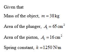
The drawing shows a hydsraulic chamber with a spring (string constant = 1250N/m) attached to the input piston and an object of 38 kg (resting on the output plunger). The piston and plunger are at the same height each having a negligible mass. By how much is the spring compressed from its unstrined position?
The drawing shows a hydsraulic chamber with a spring (string constant = 1250N/m) attached to the input piston and an object of 38 kg (resting on the output plunger). The piston and plunger are at the same height each having a negligible mass. By how much is the spring compressed from its unstrined position?
Related questions
Question
100%
The drawing shows a hydsraulic chamber with a spring (string constant = 1250N/m) attached to the input piston and an object of 38 kg (resting on the output plunger). The piston and plunger are at the same height each having a negligible mass.
By how much is the spring compressed from its unstrined position?

Transcribed Image Text:The image depicts a simple mechanical setup with two connected chambers of different sizes, indicating a principle of fluid mechanics or pressure distribution.
### Diagram Explanation:
- The diagram shows a container divided into two parts with different cross-sectional areas.
- The left chamber has a cross-sectional area of **15 cm²** and is connected to a spring mechanism.
- The right chamber has a larger cross-sectional area of **65 cm²**.
- Both chambers are filled with a fluid, and there is a floating object depicted in the right chamber.
### Mechanical Setup:
- **Spring Mechanism:** The left chamber has a spring placed above it, which could indicate a pressure or force being applied downwards.
- **Floating Object:** In the right chamber, a spherical object is floating on the surface of the fluid. This can represent buoyancy or displaced fluid volume discussion.
### Educational Applications:
This setup is often used to demonstrate principles such as Pascal's Law, which states that pressure applied to a confined fluid is transmitted undiminished throughout the fluid. It can also illustrate concepts of buoyancy and fluid displacement.
### Key Points for Learning:
- **Pressure Differences:** Understand how different areas can affect pressures within the system.
- **Applications of Mechanics:** Explore how forces such as spring compression can impact fluid behavior.
- **Real-life Examples:** Consider how this setup relates to hydraulic systems and other real-world applications.
Expert Solution
Step 1

Trending now
This is a popular solution!
Step by step
Solved in 2 steps with 2 images
