Series of free-body diagrams and equilibrium equations to determine important reactions/loads imparted on the components of the machine during typical use
Series of free-body diagrams and equilibrium equations to determine important reactions/loads imparted on the components of the machine during typical use

Elements Of Electromagnetics
7th Edition
ISBN:9780190698614
Author:Sadiku, Matthew N. O.
Publisher:Sadiku, Matthew N. O.
ChapterMA: Math Assessment
Section: Chapter Questions
Problem 1.1MA

Related questions

Question
Series of free-body diagrams and equilibrium equations to determine important reactions/loads imparted on the components of the machine during typical use

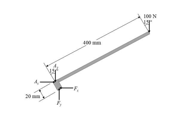
Transcribed Image Text:The diagram illustrates a mechanical plier with various annotated dimensions and force angles, likely used for educational purposes to study static equilibrium or mechanical advantage.
### Components and Dimensions:
- **Handles:**
- Two handles, each 400 mm in length, are shown extending from the pivot point.
- At the end of each handle, a 100 N force is applied at a 15° angle from the horizontal.
- **Force Application:**
- The forces on both handles are applied downwards at the same angle.
- **Pivot and Linkage:**
- The tool pivots around point C.
- A linkage mechanism is formed by points A, B, D, E, and F.
- **Annotated Points and Distances:**
- **Point A** is at the pivot near the jaws of the plier.
- **Point B** is connected to the linkage system.
- **Point C** is the main pivot point of the plier.
- **Point D** is at the terminus of the shorter 30 mm segment from point E.
- **Point E** is connected perpendicularly to the outer fulcrum or jaw.
- **Point F** marks the attachment of the inner linkage to the handles.
- The distance from point E to C is 80 mm, and the internal linkage segment BF and DF each measure 20 mm.
- **Jaws:**
- The front part, likely the jaws of the plier, is marked with point J, with a short 15 mm segment leading to a smaller inner adjustment or support marked with "realizes."
### Mechanical Function:
The diagram appears to demonstrate the mechanical advantage of the plier by showing how forces applied at the handles can exert greater force at points E and F due to the lever action and linkage configuration. This setup helps explain concepts like torque, equilibrium, and mechanical advantage in a practical tool, useful for engineering or physics education.
Expert Solution
Step 1
Consider the free body diagram of the handle as shown below.
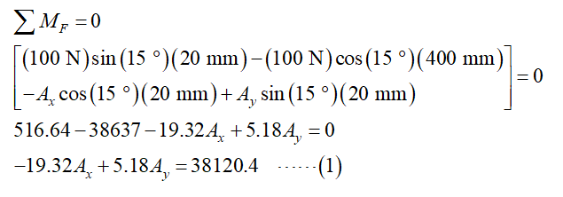
Step 2
From the free body diagram of handle, take moment equilibrium about the point F.
Step 3
Consider the free body diagram of the jaw.
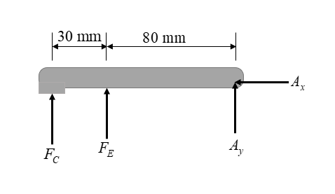
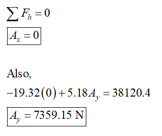
From the horizontal equilibrium of forces,

Step by step
Solved in 5 steps with 7 images

Knowledge Booster


Learn more about
Need a deep-dive on the concept behind this application? Look no further. Learn more about this topic, mechanical-engineering and related others by exploring similar questions and additional content below.Recommended textbooks for you
Elements Of Electromagnetics
Mechanical Engineering
ISBN:
9780190698614
Author:
Sadiku, Matthew N. O.
Publisher:
Oxford University Press

Mechanics of Materials (10th Edition)
Mechanical Engineering
ISBN:
9780134319650
Author:
Russell C. Hibbeler
Publisher:
PEARSON

Thermodynamics: An Engineering Approach
Mechanical Engineering
ISBN:
9781259822674
Author:
Yunus A. Cengel Dr., Michael A. Boles
Publisher:
McGraw-Hill Education
Elements Of Electromagnetics
Mechanical Engineering
ISBN:
9780190698614
Author:
Sadiku, Matthew N. O.
Publisher:
Oxford University Press
Mechanics of Materials (10th Edition)
Mechanical Engineering
ISBN:
9780134319650
Author:
Russell C. Hibbeler
Publisher:
PEARSON
Thermodynamics: An Engineering Approach
Mechanical Engineering
ISBN:
9781259822674
Author:
Yunus A. Cengel Dr., Michael A. Boles
Publisher:
McGraw-Hill Education

Control Systems Engineering
Mechanical Engineering
ISBN:
9781118170519
Author:
Norman S. Nise
Publisher:
WILEY

Mechanics of Materials (MindTap Course List)
Mechanical Engineering
ISBN:
9781337093347
Author:
Barry J. Goodno, James M. Gere
Publisher:
Cengage Learning

Engineering Mechanics: Statics
Mechanical Engineering
ISBN:
9781118807330
Author:
James L. Meriam, L. G. Kraige, J. N. Bolton
Publisher:
WILEY