Calcuate torsion From Point A to Point C, Calcuate Bending From Point A to Point B and Point A to Point C. Draw a FBD from point A to point B and another for point A to C indicating what stresses are been calculate. Use the stress tensor and stress cube to Indicate what forces are acting at point A. Force apply at point B is 70lb Distacen from Point A to B is 12 in or 1 feet long Distacen from Point A to C is 3 in Handle diameter 0.625 in
Calcuate torsion From Point A to Point C, Calcuate Bending From Point A to Point B and Point A to Point C. Draw a FBD from point A to point B and another for point A to C indicating what stresses are been calculate. Use the stress tensor and stress cube to Indicate what forces are acting at point A. Force apply at point B is 70lb Distacen from Point A to B is 12 in or 1 feet long Distacen from Point A to C is 3 in Handle diameter 0.625 in

Elements Of Electromagnetics
7th Edition
ISBN:9780190698614
Author:Sadiku, Matthew N. O.
Publisher:Sadiku, Matthew N. O.
ChapterMA: Math Assessment
Section: Chapter Questions
Problem 1.1MA

Related questions
Question
Calcuate torsion From Point A to Point C, Calcuate Bending From Point A to Point B and Point A to Point C. Draw a FBD from point A to point B and another for point A to C indicating what stresses are been calculate. Use the stress tensor and stress cube to Indicate what forces are acting at point A.
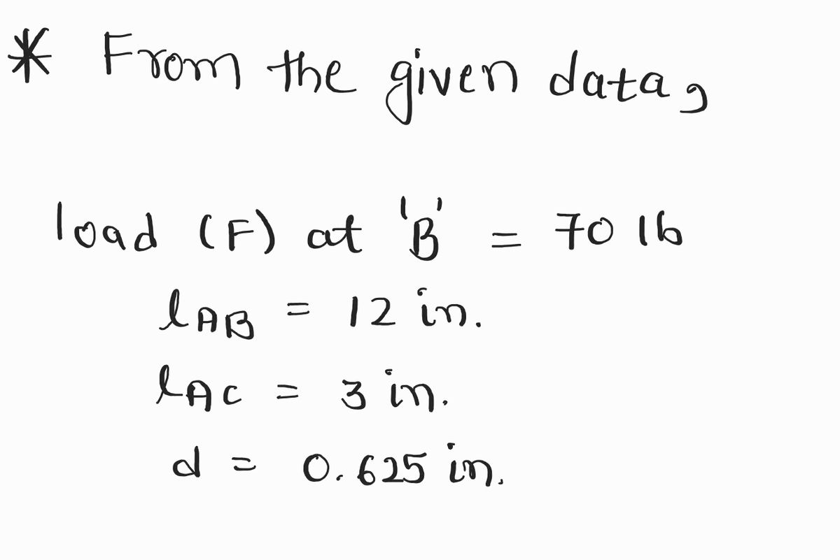
Force apply at point B is 70lb
Distacen from Point A to B is 12 in or 1 feet long
Distacen from Point A to C is 3 in
Handle diameter 0.625 in

Transcribed Image Text:### Overview
This diagram illustrates the mechanics of using a lug wrench to remove or tighten lug nuts on a tire. It provides a clear depiction of the leverage involved and the forces applied.
### Diagram Explanation
1. **Upper Portion:**
- **Axle:** The horizontal section at the top represents the axle on which the tire is mounted.
- **Lug Wrench (AB):** A tool used to apply torque to lug nuts, shown in an "L" shape with points marked A and B.
- The vertical arrow labeled "3 in" indicates the length or distance from point A to the axle, representing leverage.
2. **Forces and Mechanics:**
- **Point A:** The pivot or fulcrum where the wrench is attached to the lug nut.
- **Point B:** The end of the wrench where force is applied.
- The downward arrow labeled "F" shows the force applied at the end of the wrench to create torque.
3. **Lower Portion:**
- **Tire:** A frontal view of the wheel shows the lug nuts arranged in a circle.
- **Arrow from Point A:** Another arrow originating from A indicates the direction of the force applied when using the wrench.
- The red arrow labeled "F" also shows the rotational force applied to loosen or tighten the lug nut, further emphasizing the torque concept.
### Educational Focus
- **Leverage and Torque:** This diagram is an educational representation of how torque is used in practical applications. It shows how applying force at a certain distance from a pivot point increases the rotational effect, making it easier to turn the lug nut.
- **Practical Mechanics:** Understanding how to properly use a lug wrench is essential for tasks like changing a tire, where the principles of physics are applied for efficient and effective manual labor.
Expert Solution
Step 1: Given data
For the solution refer below images.
- Find F.B.D. and shear and bending diagrams for portions AB and BC.
- Find stress tensor at A.

Step by step
Solved in 5 steps with 7 images

Knowledge Booster


Learn more about
Need a deep-dive on the concept behind this application? Look no further. Learn more about this topic, mechanical-engineering and related others by exploring similar questions and additional content below.Recommended textbooks for you
Elements Of Electromagnetics
Mechanical Engineering
ISBN:
9780190698614
Author:
Sadiku, Matthew N. O.
Publisher:
Oxford University Press

Mechanics of Materials (10th Edition)
Mechanical Engineering
ISBN:
9780134319650
Author:
Russell C. Hibbeler
Publisher:
PEARSON

Thermodynamics: An Engineering Approach
Mechanical Engineering
ISBN:
9781259822674
Author:
Yunus A. Cengel Dr., Michael A. Boles
Publisher:
McGraw-Hill Education
Elements Of Electromagnetics
Mechanical Engineering
ISBN:
9780190698614
Author:
Sadiku, Matthew N. O.
Publisher:
Oxford University Press
Mechanics of Materials (10th Edition)
Mechanical Engineering
ISBN:
9780134319650
Author:
Russell C. Hibbeler
Publisher:
PEARSON
Thermodynamics: An Engineering Approach
Mechanical Engineering
ISBN:
9781259822674
Author:
Yunus A. Cengel Dr., Michael A. Boles
Publisher:
McGraw-Hill Education

Control Systems Engineering
Mechanical Engineering
ISBN:
9781118170519
Author:
Norman S. Nise
Publisher:
WILEY

Mechanics of Materials (MindTap Course List)
Mechanical Engineering
ISBN:
9781337093347
Author:
Barry J. Goodno, James M. Gere
Publisher:
Cengage Learning

Engineering Mechanics: Statics
Mechanical Engineering
ISBN:
9781118807330
Author:
James L. Meriam, L. G. Kraige, J. N. Bolton
Publisher:
WILEY