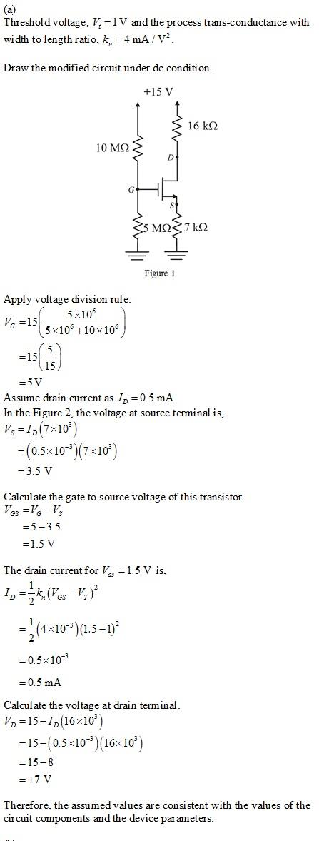
(a) If the transistor has V, = 1 V, and k, = 4 mA/V’, verify that the bias circuit establishes Vgs = 1.5 V, I, = 0.5 mA, and V, = +7.0 V. That is, assume these values, and %3D %3D verify that they are consistent with the values of the circuit components and the device parameters. (b) Find g and r, if V, = 100 V. (c) Draw a complete small-signal equivalent circuit for the amplifier, assuming all capacitors behave as short circuits at signal frequencies. (d) Find R, V/v.jg+ v,/v» and v,/vig-
(a) If the transistor has V, = 1 V, and k, = 4 mA/V’, verify that the bias circuit establishes Vgs = 1.5 V, I, = 0.5 mA, and V, = +7.0 V. That is, assume these values, and %3D %3D verify that they are consistent with the values of the circuit components and the device parameters. (b) Find g and r, if V, = 100 V. (c) Draw a complete small-signal equivalent circuit for the amplifier, assuming all capacitors behave as short circuits at signal frequencies. (d) Find R, V/v.jg+ v,/v» and v,/vig-

Introductory Circuit Analysis (13th Edition)
13th Edition
ISBN:9780133923605
Author:Robert L. Boylestad
Publisher:Robert L. Boylestad
Chapter1: Introduction
Section: Chapter Questions
Problem 1P: Visit your local library (at school or home) and describe the extent to which it provides literature...

Related questions
Question

Transcribed Image Text:7.33 Figure P7.33 shows a discrete-circuit amplifier. The
input signal vig is coupled to the gate through a very
large capacitor (shown as infinite). The transistor source is
connected to ground at signal frequencies via a very large
capacitor (shown as infinite). The output voltage signal that
develops at the drain is coupled to a load resistance via a very
large capacitor (shown as infinite). All capacitors behave as
short circuits for signals and as open circuits for de.
(a) If the transistor has V, = 1 V, and k, = 4 mA/V', verify
that the bias circuit establishes Ves = 1.5 V, I, =0.5 mA,
and V, = +7.0 v. That is, assume these values, and
%3D
verify that they are consistent with the values of the
circuit components and the device parameters.
(b) Find g„, and r, if V, = 100 V.
(c) Draw a complete small-signal equivalent circuit for
the amplifier, assuming all capacitors behave as short
circuits at signal frequencies.
(d) Find R, V/vig, v,/Vg» and v,/vig-
+15 V
10 MN
16 k2
Rie = 200 k)
16 kN
Vaig
5 ΜΩ
7 kN
Rin
Figure P7.33
Expert Solution
Step 1

Trending now
This is a popular solution!

Step by step
Solved in 2 steps with 2 images

Knowledge Booster


Learn more about
Need a deep-dive on the concept behind this application? Look no further. Learn more about this topic, electrical-engineering and related others by exploring similar questions and additional content below.Recommended textbooks for you
Introductory Circuit Analysis (13th Edition)
Electrical Engineering
ISBN:
9780133923605
Author:
Robert L. Boylestad
Publisher:
PEARSON

Delmar's Standard Textbook Of Electricity
Electrical Engineering
ISBN:
9781337900348
Author:
Stephen L. Herman
Publisher:
Cengage Learning

Programmable Logic Controllers
Electrical Engineering
ISBN:
9780073373843
Author:
Frank D. Petruzella
Publisher:
McGraw-Hill Education
Introductory Circuit Analysis (13th Edition)
Electrical Engineering
ISBN:
9780133923605
Author:
Robert L. Boylestad
Publisher:
PEARSON
Delmar's Standard Textbook Of Electricity
Electrical Engineering
ISBN:
9781337900348
Author:
Stephen L. Herman
Publisher:
Cengage Learning
Programmable Logic Controllers
Electrical Engineering
ISBN:
9780073373843
Author:
Frank D. Petruzella
Publisher:
McGraw-Hill Education

Fundamentals of Electric Circuits
Electrical Engineering
ISBN:
9780078028229
Author:
Charles K Alexander, Matthew Sadiku
Publisher:
McGraw-Hill Education

Electric Circuits. (11th Edition)
Electrical Engineering
ISBN:
9780134746968
Author:
James W. Nilsson, Susan Riedel
Publisher:
PEARSON

Engineering Electromagnetics
Electrical Engineering
ISBN:
9780078028151
Author:
Hayt, William H. (william Hart), Jr, BUCK, John A.
Publisher:
Mcgraw-hill Education,