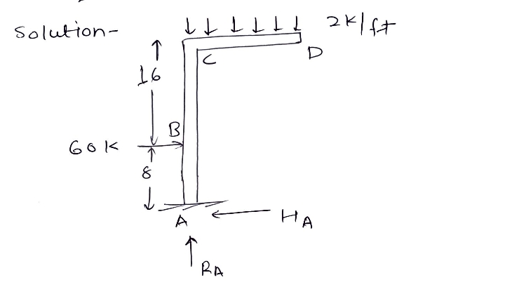
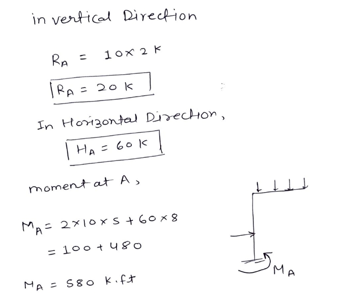
10 ft 2k/ft D 16 ft В 60 k 8 ft A Prob 2) Draw the moment diagram for the real loads on the structure shown. Draw it on the TENSION side of the structure.
10 ft 2k/ft D 16 ft В 60 k 8 ft A Prob 2) Draw the moment diagram for the real loads on the structure shown. Draw it on the TENSION side of the structure.
Steel Design (Activate Learning with these NEW titles from Engineering!)
6th Edition
ISBN:9781337094740
Author:Segui, William T.
Publisher:Segui, William T.
Chapter5: Beams
Section: Chapter Questions
Problem 5.13.2P
Related questions
Question
100%

Transcribed Image Text:### Structural Analysis Problem
**Diagram Description:**
- **Structure Type:** L-shaped frame with a vertical and horizontal segment.
- **Vertical Section (AB):**
- Height: 24 ft
- Load at B: 60 kips horizontal force towards the frame
- **Horizontal Section (CD):**
- Length: 10 ft
- Distributed Load: 2 kips/ft downwards
**Support and Joints:**
- **Point A:** Fixed support at the base.
- **Point C:** Joint connecting the vertical and horizontal segments.
- **Point D:** Free end of the horizontal segment.
**Objective:**
- **Problem 2:** Draw the moment diagram for the actual loads on the structure.
- **Requirement:** Illustrate the moment diagram on the tension side of the structure.
This exercise involves calculating the bending moments at key points on the structure, considering the effects of the applied loads. Understanding and constructing moment diagrams are crucial for assessing how forces affect structures and ensuring structural safety and integrity.
Expert Solution
Step 1


Step by step
Solved in 2 steps with 4 images

Knowledge Booster
Learn more about
Need a deep-dive on the concept behind this application? Look no further. Learn more about this topic, civil-engineering and related others by exploring similar questions and additional content below.Recommended textbooks for you

Steel Design (Activate Learning with these NEW ti…
Civil Engineering
ISBN:
9781337094740
Author:
Segui, William T.
Publisher:
Cengage Learning

Architectural Drafting and Design (MindTap Course…
Civil Engineering
ISBN:
9781285165738
Author:
Alan Jefferis, David A. Madsen, David P. Madsen
Publisher:
Cengage Learning

Construction Materials, Methods and Techniques (M…
Civil Engineering
ISBN:
9781305086272
Author:
William P. Spence, Eva Kultermann
Publisher:
Cengage Learning

Steel Design (Activate Learning with these NEW ti…
Civil Engineering
ISBN:
9781337094740
Author:
Segui, William T.
Publisher:
Cengage Learning

Architectural Drafting and Design (MindTap Course…
Civil Engineering
ISBN:
9781285165738
Author:
Alan Jefferis, David A. Madsen, David P. Madsen
Publisher:
Cengage Learning

Construction Materials, Methods and Techniques (M…
Civil Engineering
ISBN:
9781305086272
Author:
William P. Spence, Eva Kultermann
Publisher:
Cengage Learning

Materials Science And Engineering Properties
Civil Engineering
ISBN:
9781111988609
Author:
Charles Gilmore
Publisher:
Cengage Learning