
Concept explainers
Videos
Draw a suitable tree and use general loop analysis to find i10 in the circuit of (a) Fig. A1.13a by writing just one equation with i10 as the variable; (b) Fig. A1.13b by writing just two equations with i10 and i3 as the variables.
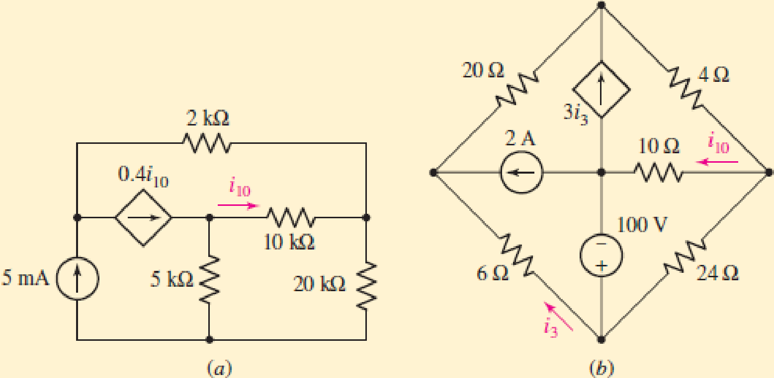
(a)
The value of the current
Answer to Problem 2P
The value of the current
Explanation of Solution
Given data:
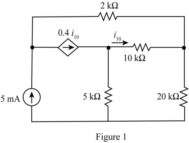
The given diagram is shown in Figure 1.
Calculation:
Draw the tree diagram of the given network.
The required diagram is shown in Figure 2.
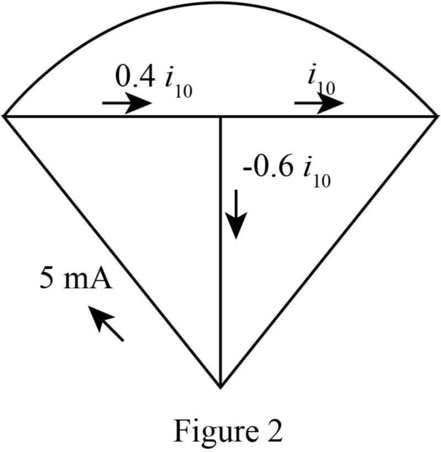
The current
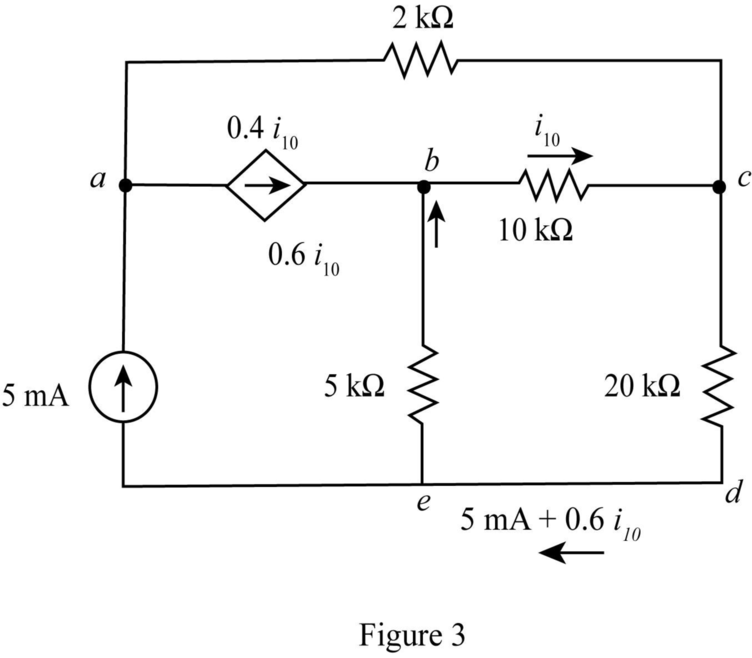
The modified diagram is shown in Figure 3.
The conversion from
The conversion from
The conversion from
The conversion from
The conversion from
The conversion from
Write the KVL for the loop
The conversion from
The conversion from
Hence, the current
Conclusion:
Therefore, the value of the current
(b)
The value of the current
Answer to Problem 2P
The value of the current
Explanation of Solution
Given data:
The given diagram is shown in Figure 4.
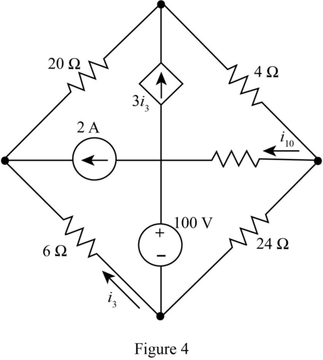
Calculation:
Draw tree diagram for the given network.
The required diagram is shown in Figure 5.
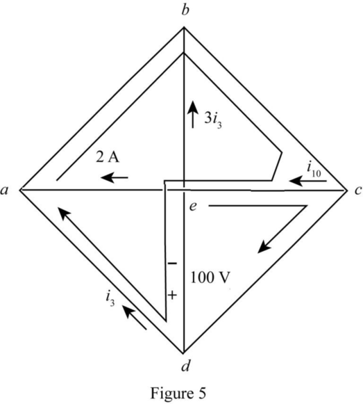
Write the KVL for the loop
Write the KVL for the loop
Substitute
Conclusion:
Therefore, the value of the current
Want to see more full solutions like this?
Chapter A1 Solutions
Loose Leaf for Engineering Circuit Analysis Format: Loose-leaf
Additional Engineering Textbook Solutions
Vector Mechanics For Engineers
Electric Circuits. (11th Edition)
BASIC BIOMECHANICS
Starting Out with Java: From Control Structures through Data Structures (4th Edition) (What's New in Computer Science)
Modern Database Management
Introduction To Programming Using Visual Basic (11th Edition)


- Figure 2 3) *** The circuit of Figure 3 is designed with W/L = 20/0.18, λ= 0, and ID = 0.25 mA. (Optional- 20 points) a) Compute the required gate bias voltage. b) With such a gate voltage, how much can W/L be increased while M1 remains in saturation? What is the maximum voltage gain that can be achieved as W/L increases? VDD = 1.8 V RD 2k - Vout Vin M₁ Figure 3arrow_forward1) Rs = 4kQ, R₁ = 850 kQ, R₂ = 350 kQ, and R₁ = 4 kQ. The transistor parameters are VTP = -12 V, K'p = 40 µA / V², W/L = 80, and λ = 0.05 V-1. (50 Points) a) Determine IDQ and VSDQ. b) Find the small signal voltage gain. (Av) c) Determine the small signal circuit transconductance gain. (Ag = io/vi) d) Find the small signal output resistance. VDD = 10 V 2'; www www Figure 1 Ссarrow_forwardQ11arrow_forward
- 2) The transistor parameters of the NMOS device in the common-gate amplifier in Figure 2 are VTN = 0.4V, K'n = 100 μA / V², and λ=0. (50 points) a) Find RD such that VDSQ = VDs (sat) + 0.25V. b) Determine the transistor W/L ratio such that the small-signal voltage gain is Av=6. c) What is the value of VGSQ? Сс 2 mA Rp T V=-1.8 V V+= 1.8 V Figure 2arrow_forwardCalculate the percent voltage regulation for a three-phase wye-connected 2500 kVA 6600-V turboalternator operating at full-load Unity power factor The per phase synchronous reactance and the armature resistance are 10.4 2 and 0.071 ≤2, respectively?arrow_forwardDon't use ai to answer I will report you answerarrow_forward
 Introductory Circuit Analysis (13th Edition)Electrical EngineeringISBN:9780133923605Author:Robert L. BoylestadPublisher:PEARSON
 Delmar's Standard Textbook Of ElectricityElectrical EngineeringISBN:9781337900348Author:Stephen L. HermanPublisher:Cengage Learning
 Programmable Logic ControllersElectrical EngineeringISBN:9780073373843Author:Frank D. PetruzellaPublisher:McGraw-Hill Education
 Fundamentals of Electric CircuitsElectrical EngineeringISBN:9780078028229Author:Charles K Alexander, Matthew SadikuPublisher:McGraw-Hill Education
 Electric Circuits. (11th Edition)Electrical EngineeringISBN:9780134746968Author:James W. Nilsson, Susan RiedelPublisher:PEARSON
 Engineering ElectromagneticsElectrical EngineeringISBN:9780078028151Author:Hayt, William H. (william Hart), Jr, BUCK, John A.Publisher:Mcgraw-hill Education,