
Mechanics of Materials Plus Mastering Engineering with Pearson eText - Access Card Package (10th Edition)
10th Edition
ISBN: 9780134518121
Author: Russell C. Hibbeler
Publisher: PEARSON
expand_more
expand_more
format_list_bulleted
Concept explainers
Videos
Textbook Question
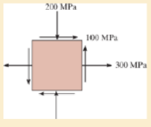
Chapter 9.3, Problem 9.14P
Determine (a) the principal stresses and (b) the maximum in-plane shear stress and average normal stress at the point. Specify the orientation of the element in each case.
Expert Solution & Answer
Want to see the full answer?
Check out a sample textbook solution
Students have asked these similar questions
Please show All work and fill it in thermodynamics
Quick solution required.
My request, Don't use Ai.
Mechanical engineering
Please give handwritten solution, don't use chatgpt.
Fbd should be included
Chapter 9 Solutions
Mechanics of Materials Plus Mastering Engineering with Pearson eText - Access Card Package (10th Edition)
Ch. 9.3 - In each case, the state of stress x, y, xy...Ch. 9.3 - Given the state of stress shown on the element,...Ch. 9.3 - Determine the normal stress and shear stress...Ch. 9.3 - Determine the equivalent state of stress on an...Ch. 9.3 - Also, find the corresponding orientation of the...Ch. 9.3 - Determine the equivalent state of stress on an...Ch. 9.3 - Determine the maximum principal stress at point B.Ch. 9.3 - Determine the principal stress at point C.Ch. 9.3 - Prove that the sum of the normal stresses x + y =...Ch. 9.3 - Determine the stress components acting on the...
Ch. 9.3 - Determine the stress components acting on the...Ch. 9.3 - Determine the normal stress and shear stress...Ch. 9.3 - Determine the normal stress and shear stress...Ch. 9.3 - Determine the stress components acting on the...Ch. 9.3 - Determine the stress components acting on the...Ch. 9.3 - Solve Prob.97 using the stress transformation...Ch. 9.3 - Determine the stress components acting on the...Ch. 9.3 - Solve Prob.99 using the stress transformation...Ch. 9.3 - Determine the equivalent state of stress on an...Ch. 9.3 - Determine the equivalent slate of stress on an...Ch. 9.3 - Determine the stress components acting on the...Ch. 9.3 - Determine (a) the principal stresses and (b) the...Ch. 9.3 - The state of stress at a point is shown on the...Ch. 9.3 - Determine the equivalent state of stress on an...Ch. 9.3 - Determine the equivalent state of stress on an...Ch. 9.3 - A point on a thin plate is subjected to the two...Ch. 9.3 - Determine the equivalent state of stress on an...Ch. 9.3 - The stress along two planes at a point is...Ch. 9.3 - The stress acting on two planes at a point is...Ch. 9.3 - The state of stress at a point in a member is...Ch. 9.3 - The grains of wood in the board make an angle of...Ch. 9.3 - The wood beam is subjected to a load of 12 kN. If...Ch. 9.3 - The internal loadings at a section of the beam are...Ch. 9.3 - Solve Prob.925 for point B. 925. The internal...Ch. 9.3 - Solve Prob.925 for point C. 925. The internal...Ch. 9.3 - It is subjected to a torque of 12 kip in. and a...Ch. 9.3 - The bell crank is pinned at A and supported by a...Ch. 9.3 - The beam has a rectangular cross section and is...Ch. 9.3 - A paper tube is formed by rolling a cardboard...Ch. 9.3 - Solve Prob.931 for the normal stress acting...Ch. 9.3 - The 2-in.-diameter drive shaft AB on the...Ch. 9.3 - Determine the principal stresses in the...Ch. 9.3 - The internal loadings at a cross section through...Ch. 9.3 - The internal loadings at a cross section through...Ch. 9.3 - The shaft has a diameter d and is subjected to the...Ch. 9.3 - The steel pipe has an inner diameter of 2.75 in....Ch. 9.3 - Solve Prob.938 for point B, w1ich is located on...Ch. 9.3 - The wide-flange beam is subjected to the 50-kN...Ch. 9.3 - Solve Pro b. 9-40 for point B located on the web...Ch. 9.3 - The box beam is subjected to the 26-kN force that...Ch. 9.3 - Solve Prob.942 for point B. 942. The box beam is...Ch. 9.4 - Use Mohrs circle to determine the normal stress...Ch. 9.4 - Also, find the corresponding orientation of the...Ch. 9.4 - Draw Mohrs circle and determine the principal...Ch. 9.4 - Determine the principal stresses at a point on the...Ch. 9.4 - Determine the principal stresses at point A on the...Ch. 9.4 - Point A is just below the flange.Ch. 9.4 - Solve Prob.9-2 using Mohrs circle. 92. Determine...Ch. 9.4 - Solve Prob.93 using Mohrs circle. 93. Determine...Ch. 9.4 - Solve Prob.96 using Mohrs circle. 96. Determine...Ch. 9.4 - Solve Prob.911 using Mohrs circle. 911. Determine...Ch. 9.4 - Solve Prob.915 using Mohrs circle. 915. The state...Ch. 9.4 - Solve Prob.916 using Mohrs circle. 916. Determine...Ch. 9.4 - Mohrs circle for the state of stress is shown in...Ch. 9.4 - Determine (a) the principal stresses and (b) the...Ch. 9.4 - Determine (a) the principal stresses and (b) the...Ch. 9.4 - Determine the equivalent state of stress if an...Ch. 9.4 - Draw Mohrs circle that describes each of the...Ch. 9.4 - Draw Mohrs circle trial describes each of the...Ch. 9.4 - Determine (a) the principal stresses and (b) the...Ch. 9.4 - Determine (a) the principal stresses and (b) the...Ch. 9.4 - Determine (a) the principal stresses and (b) the...Ch. 9.4 - Determine (a) the principal stresses and (b) the...Ch. 9.4 - Determine (a) the principal stresses and (b) the...Ch. 9.4 - Draw Mohrs circle that describes each of the...Ch. 9.4 - The grains of wood in the board make an angle of...Ch. 9.4 - The post is fixed supported at its base and a...Ch. 9.4 - Determine the principal stresses, the maximum...Ch. 9.4 - The thin-walled pipe has an inner diameter of 0.5...Ch. 9.4 - The frame supports the triangular distributed load...Ch. 9.4 - The frame supports the triangular distributed load...Ch. 9.4 - The rotor shaft of the helicopter is subjected to...Ch. 9.4 - The pedal crank for a bicycle has the cross...Ch. 9.4 - A spherical pressure vessel has an inner radius of...Ch. 9.4 - The cylindrical pressure vessel has an inner...Ch. 9.4 - Determine the normal and shear stresses at point D...Ch. 9.4 - Determine the principal stress at point D, Which...Ch. 9.4 - If the box wrench is subjected to the 50 lb force,...Ch. 9.4 - If the box wrench is subjected to the 50-lb force,...Ch. 9.4 - The post is fixed supported at its base and the...Ch. 9.5 - Draw the three Mohrs circles that describe each of...Ch. 9.5 - Draw the three Mohrs circles that describe the...Ch. 9.5 - Draw the three Mohrs circles that describe the...Ch. 9.5 - Determine the principal stresses and the absolute...Ch. 9.5 - Determine the principal stresses and the absolute...Ch. 9.5 - Determine the principal stresses and the absolute...Ch. 9.5 - Determine the principal stresses and the absolute...Ch. 9.5 - The solid shaft is subjected to a torque, bending...Ch. 9.5 - The frame is subjected to a horizontal force and...Ch. 9.5 - The bolt is fixed to its support at C. If a force...Ch. 9.5 - The bolt is fixed to its support at C. If a force...Ch. 9 - Prob. 9.1RPCh. 9 - The steel pipe has an inner diameter of 2.75 in....Ch. 9 - Determine the equivalent state of stress If an...Ch. 9 - The crane is used to support the 350-lb load....Ch. 9 - Determine the equivalent state of stress on an...Ch. 9 - The propeller shaft of the tugboat is subjected to...Ch. 9 - Determine the principal stresses in the box beam...Ch. 9 - Determine (a) the principal stresses and (b) the...Ch. 9 - Determine the stress components acting on the...
Knowledge Booster


Learn more about
Need a deep-dive on the concept behind this application? Look no further. Learn more about this topic, mechanical-engineering and related others by exploring similar questions and additional content below.Similar questions
- (I) [40 Points] Using centered finite difference approximations as done in class, solve the equation for O: d20 dx² + 0.010+ Q=0 subject to the boundary conditions shown in the stencil below. Do this for two values of Q: (a) Q = 0.3, and (b) Q= √(0.5 + 2x)e-sinx (cos(5x)+x-0.5√1.006-x| + e −43*|1+.001+x* | * sin (1.5 − x) + (cosx+0.001 + ex-1250+ sin (1-0.9x)|) * x - 4.68x4. For Case (a) (that is, Q = 0.3), use the stencil in Fig. 1. For Case (b), calculate with both the stencils in Fig. 1 and Fig 2. For all the three cases, show a table as well as a plot of O versus x. Discuss your results. Use MATLAB and hand in the MATLAB codes. 1 0=0 x=0 2 3 4 0=1 x=1 Fig 1 1 2 3 4 5 6 7 8 9 10 11 0=0 x=0 0=1 x=1 Fig 2arrow_forwardFig 2 (II) [60 Points] Using centered finite difference approximation as done in class, solve the equation: 020 020 + მx2 მy2 +0.0150+Q=0 subject to the boundary conditions shown in the stencils below. Do this for two values of Q: (a) Q = 0.3, and (b) Q = 10.5x² + 1.26 * 1.5 x 0.002 0.008. For Case (a) (that is, Q = 0.3) use Fig 3. For Case (b), use both Fig. 3 and Fig 4. For all the three cases, show a table as well as the contour plots of versus (x, y), and the (x, y) heat flux values at all the nodes on the boundaries x = 1 and y = 1. Discuss your results. Use MATLAB and hand in the MATLAB codes. (Note that the domain is (x, y)e[0,1] x [0,1].) 0=0 0=0 4 8 12 16 10 Ꮎ0 15 25 9 14 19 24 3 11 15 0=0 8-0 0=0 3 8 13 18 23 2 6 сл 5 0=0 10 14 6 12 17 22 1 6 11 16 21 13 e=0 Fig 3 Fig 4 Textbook: Numerical Methods for Engineers, Steven C. Chapra and Raymond P. Canale, McGraw-Hill, Eighth Edition (2021).arrow_forwardShip construction question. Sketch and describe the forward arrangements of a ship. Include componets of the structure and a explanation of each part/ term. Ive attached a general fore end arrangement. Simplfy construction and give a brief describion of the terms.arrow_forward
- Problem 1 Consider R has a functional relationship with variables in the form R = K xq xx using show that n ✓ - (OR 1.) = i=1 2 Их Ux2 Ихэ 2 (177)² = ² (1)² + b² (12)² + c² (1)² 2 UR R x2 x3arrow_forward4. Figure 3 shows a crank loaded by a force F = 1000 N and Mx = 40 Nm. a. Draw a free-body diagram of arm 2 showing the values of all forces, moments, and torques that act due to force F. Label the directions of the coordinate axes on this diagram. b. Draw a free-body diagram of arm 2 showing the values of all forces, moments, and torques that act due to moment Mr. Label the directions of the coordinate axes on this diagram. Draw a free body diagram of the wall plane showing all the forces, torques, and moments acting there. d. Locate a stress element on the top surface of the shaft at A and calculate all the stress components that act upon this element. e. Determine the principal stresses and maximum shear stresses at this point at A.arrow_forward3. Given a heat treated 6061 aluminum, solid, elliptical column with 200 mm length, 200 N concentric load, and a safety factor of 1.2, design a suitable column if its boundary conditions are fixed-free and the ratio of major to minor axis is 2.5:1. (Use AISC recommended values and round the ellipse dimensions so that both axes are whole millimeters in the correct 2.5:1 ratio.)arrow_forward
- 1. A simply supported shaft is shown in Figure 1 with w₁ = 25 N/cm and M = 20 N cm. Use singularity functions to determine the reactions at the supports. Assume El = 1000 kN cm². Wo M 0 10 20 30 40 50 60 70 80 90 100 110 cm Figure 1 - Problem 1arrow_forwardPlease AnswerSteam enters a nozzle at 400°C and 800 kPa with a velocity of 10 m/s and leaves at 375°C and 400 kPa while losing heat at a rate of 26.5 kW. For an inlet area of 800 cm2, determine the velocity and the volume flow rate of the steam at the nozzle exit. Use steam tables. The velocity of the steam at the nozzle exit is m/s. The volume flow rate of the steam at the nozzle exit is m3/s.arrow_forward2. A support hook was formed from a rectangular bar. Find the stresses at the inner and outer surfaces at sections just above and just below O-B. -210 mm 120 mm 160 mm 400 N B thickness 8 mm = Figure 2 - Problem 2arrow_forward
- Steam flows steadily through a turbine at a rate of 45,000 lbm/h, entering at 1000 psia and 900°F and leaving at 5 psia as saturated vapor. If the power generated by the turbine is 4.1 MW, determine the rate of heat loss from the steam. The enthalpies are h1 = 1448.6 Btu/lbm and h2 = 1130.7 Btu/lbm. The rate of heat loss from the steam is Btu/s.arrow_forwardThe A/D converter wit the specifications listed below is planned to be used in an environment in which the A/D converter temperature may change by ± 10 °C. Estimate the contributions of conversion and quantization errors to the uncertainty in the digital representation of an analog voltage by the converter. FSO N Linearity error Temperature drift error Analog to Digital (A/D) Converter 0-10 V 12 bits ± 3 bits 1 bit/5 °Carrow_forward6-13. A smooth tube in the form of a circle of radius r rotates in its vertical plane with a constant angular velocity w. The position of a particle of mass m that slides inside the tube is given by the relative coordinate p. Find the differential equation for . e О E g ω Figure P6-13arrow_forward
arrow_back_ios
SEE MORE QUESTIONS
arrow_forward_ios
Recommended textbooks for you
 Mechanics of Materials (MindTap Course List)Mechanical EngineeringISBN:9781337093347Author:Barry J. Goodno, James M. GerePublisher:Cengage Learning
Mechanics of Materials (MindTap Course List)
Mechanical Engineering
ISBN:9781337093347
Author:Barry J. Goodno, James M. Gere
Publisher:Cengage Learning
Understanding Stress Transformation and Mohr's Circle; Author: The Efficient Engineer;https://www.youtube.com/watch?v=_DH3546mSCM;License: Standard youtube license