
VECTOR MECHANIC
12th Edition
ISBN: 9781264095032
Author: BEER
Publisher: MCGRAW-HILL HIGHER EDUCATION
expand_more
expand_more
format_list_bulleted
Videos
Textbook Question
Chapter 9.2, Problem 9.55P
Two L76 × 76 × 6.4-mm angles are welded to a C250 × 22.8 channel. Determine the moments of inertia of the combined section with respect to centroidal axes respectively parallel and perpendicular to the web of the channel.
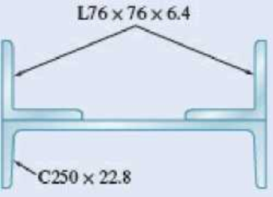
Fig. P9.55
Expert Solution & Answer
Want to see the full answer?
Check out a sample textbook solution
Students have asked these similar questions
From thermodynamics
please fill in the table show all work step by step
The 150-lb skater passes point A with a speed of 6 ft/s.
(Figure 1)
Determine his speed when he reaches point B. Neglect friction.
Determine the normal force exerted on him by the track at this point.
25 ft
B
= 4x
A
20 ft
x
A virtual experiment is designed to determine the effect of friction on the timing and speed
of packages being delivered to a conveyor belt and the normal force applied to the tube.
A package is held and then let go at the edge of a circular shaped tube of radius R = 5m.
The particle at the bottom will transfer to the conveyor belt, as shown below.
Run the simulations for μ = 0, 0.1, 0.2, 0.3, 0.4, 0.5, 0.6 and determine the time and speed at
which the package is delivered to the conveyor belt. In addition, determine the maximum
normal force and its location along the path as measured by angle 0.
Submit in hardcopy form:
(0) Free Body Diagram, equations underneath, derivations
(a) Your MATLAB mfile
(b) A table listing the values in 5 columns:
μ, T (time of transfer), V (speed of transfer), 0 (angle of max N), Nmax (max N)
(c) Based on your results, explain in one sentence what you think will happen to the
package if the friction is increased even further, e.g. μ = 0.8.
NOTE: The ODE is…
Chapter 9 Solutions
VECTOR MECHANIC
Ch. 9.1 - 9.1 through 9.4 Determine by direct integration...Ch. 9.1 - 9.1 through 9.4 Determine by direct integration...Ch. 9.1 - 9.1 through 9.4 Determine by direct integration...Ch. 9.1 - 9.1 through 9.4 Determine by direct integration...Ch. 9.1 - 9.5 through 9.8 Determine by direct integration...Ch. 9.1 - 9.5 through 9.8 Determine by direct integration...Ch. 9.1 - 9.5 through 9.8 Determine by direct integration...Ch. 9.1 - Prob. 9.8PCh. 9.1 - 9.9 through 9.11 Determine by direct integration...Ch. 9.1 - 9.9 through 9.11 Determine by direct integration...
Ch. 9.1 - Prob. 9.11PCh. 9.1 - Prob. 9.12PCh. 9.1 - 9.12 through 9.14 Determine by direct integration...Ch. 9.1 - 9.12 through 9.14 Determine by direct integration...Ch. 9.1 - Prob. 9.15PCh. 9.1 - Prob. 9.16PCh. 9.1 - Prob. 9.17PCh. 9.1 - Prob. 9.18PCh. 9.1 - Determine the moment of inertia and the radius of...Ch. 9.1 - Prob. 9.20PCh. 9.1 - Determine the polar moment of inertia and the...Ch. 9.1 - Prob. 9.22PCh. 9.1 - Prob. 9.23PCh. 9.1 - 9.23 and 9.24 Determine the polar moment of...Ch. 9.1 - Prob. 9.25PCh. 9.1 - Prob. 9.26PCh. 9.1 - Prob. 9.27PCh. 9.1 - Prob. 9.28PCh. 9.1 - Prob. 9.29PCh. 9.1 - Prove that the centroidal polar moment of inertia...Ch. 9.2 - 9.31 and 9.32 Determine the moment of inertia and...Ch. 9.2 - 9.31 and 9.32 Determine the moment of inertia and...Ch. 9.2 - 9.33 and 9.34 Determine the moment of inertia and...Ch. 9.2 - 9.33 and 9.34 Determine the moment of inertia and...Ch. 9.2 - Determine the moments of inertia of the shaded...Ch. 9.2 - Determine the moments of inertia of the shaded...Ch. 9.2 - Prob. 9.37PCh. 9.2 - Prob. 9.38PCh. 9.2 - Prob. 9.39PCh. 9.2 - Prob. 9.40PCh. 9.2 - 9.41 through 9.44 Determine the moments of inertia...Ch. 9.2 - 9.41 through 9.44 Determine the moments of inertia...Ch. 9.2 - Prob. 9.43PCh. 9.2 - Prob. 9.44PCh. 9.2 - 9.45 and 9.46 Determine the polar moment of...Ch. 9.2 - Prob. 9.46PCh. 9.2 - 9.47 and 9.48 Determine the polar moment of...Ch. 9.2 - 9.47 and 9.48 Determine the polar moment of...Ch. 9.2 - To form a reinforced box section, two rolled W...Ch. 9.2 - Two channels are welded to a d 12-in. steel plate...Ch. 9.2 - Prob. 9.51PCh. 9.2 - Two 20-mm steel plates are welded to a rolled S...Ch. 9.2 - A channel and a plate are welded together as shown...Ch. 9.2 - Prob. 9.54PCh. 9.2 - Two L76 76 6.4-mm angles are welded to a C250 ...Ch. 9.2 - Prob. 9.56PCh. 9.2 - Prob. 9.57PCh. 9.2 - 9.57 and 9.58 The panel shown forms the end of a...Ch. 9.2 - Prob. 9.59PCh. 9.2 - Prob. 9.60PCh. 9.2 - Prob. 9.61PCh. 9.2 - Prob. 9.62PCh. 9.2 - Prob. 9.63PCh. 9.2 - Prob. 9.64PCh. 9.2 - Prob. 9.65PCh. 9.2 - Prob. 9.66PCh. 9.3 - 9.67 through 9.70 Determine by direct integration...Ch. 9.3 - 9.67 through 9.70 Determine by direct integration...Ch. 9.3 - 9.67 through 9.70 Determine by direct integration...Ch. 9.3 - Prob. 9.70PCh. 9.3 - Prob. 9.71PCh. 9.3 - Prob. 9.72PCh. 9.3 - Prob. 9.73PCh. 9.3 - 9.71 through 9.74 Using the parallel-axis theorem,...Ch. 9.3 - Prob. 9.75PCh. 9.3 - 9.75 through 9.78 Using the parallel-axis theorem,...Ch. 9.3 - Prob. 9.77PCh. 9.3 - Prob. 9.78PCh. 9.3 - Determine for the quarter ellipse of Prob. 9.67...Ch. 9.3 - Determine the moments of inertia and the product...Ch. 9.3 - Determine the moments of inertia and the product...Ch. 9.3 - 9.75 through 9.78 Using the parallel-axis theorem,...Ch. 9.3 - Determine the moments of inertia and the product...Ch. 9.3 - Determine the moments of inertia and the product...Ch. 9.3 - Prob. 9.85PCh. 9.3 - 9.86 through 9.88 For the area indicated,...Ch. 9.3 - Prob. 9.87PCh. 9.3 - Prob. 9.88PCh. 9.3 - Prob. 9.89PCh. 9.3 - 9.89 and 9.90 For the angle cross section...Ch. 9.4 - Using Mohrs circle, determine for the quarter...Ch. 9.4 - Using Mohrs circle, determine the moments of...Ch. 9.4 - Prob. 9.93PCh. 9.4 - Using Mohrs circle, determine the moments of...Ch. 9.4 - Using Mohrs circle, determine the moments of...Ch. 9.4 - Using Mohrs circle, determine the moments of...Ch. 9.4 - For the quarter ellipse of Prob. 9.67, use Mohrs...Ch. 9.4 - 9.98 though 9.102 Using Mohrs circle, determine...Ch. 9.4 - Prob. 9.99PCh. 9.4 - 9.98 though 9.102 Using Mohrs circle, determine...Ch. 9.4 - Prob. 9.101PCh. 9.4 - Prob. 9.102PCh. 9.4 - Prob. 9.103PCh. 9.4 - 9.104 and 9.105 Using Mohrs circle, determine the...Ch. 9.4 - 9.104 and 9.105 Using Mohrs circle, determine the...Ch. 9.4 - For a given area, the moments of inertia with...Ch. 9.4 - it is known that for a given area Iy = 48 106 mm4...Ch. 9.4 - Prob. 9.108PCh. 9.4 - Prob. 9.109PCh. 9.4 - Prob. 9.110PCh. 9.5 - A thin plate with a mass m is cut in the shape of...Ch. 9.5 - A ring with a mass m is cut from a thin uniform...Ch. 9.5 - A thin elliptical plate has a mass m. Determine...Ch. 9.5 - The parabolic spandrel shown was cut from a thin,...Ch. 9.5 - Prob. 9.115PCh. 9.5 - Fig. P9.115 and P9.116 9.116 A piece of thin,...Ch. 9.5 - A thin plate of mass m is cut in the shape of an...Ch. 9.5 - Fig. P9.117 and P9.118 9.118 A thin plate of mass...Ch. 9.5 - Determine by direct integration the mass moment of...Ch. 9.5 - The area shown is revolved about the x axis to...Ch. 9.5 - The area shown is revolved about the x axis to...Ch. 9.5 - Determine by direct integration the mass moment of...Ch. 9.5 - Fig. P9.122 and P9.123 9.123 Determine by direct...Ch. 9.5 - Prob. 9.124PCh. 9.5 - Prob. 9.125PCh. 9.5 - Prob. 9.126PCh. 9.5 - Prob. 9.127PCh. 9.5 - Prob. 9.128PCh. 9.5 - Prob. 9.129PCh. 9.5 - Knowing that the thin cylindrical shell shown has...Ch. 9.5 - A circular hole of radius r is to be drilled...Ch. 9.5 - The cups and the arms of an anemometer are...Ch. 9.5 - Prob. 9.133PCh. 9.5 - Determine the mass moment of inertia of the 0.9-lb...Ch. 9.5 - Prob. 9.135PCh. 9.5 - Prob. 9.136PCh. 9.5 - A 2-mm thick piece of sheet steel is cut and bent...Ch. 9.5 - A section of sheet steel 0.03 in. thick is cut and...Ch. 9.5 - A corner reflector for tracking by radar has two...Ch. 9.5 - A farmer constructs a trough by welding a...Ch. 9.5 - The machine element shown is fabricated from...Ch. 9.5 - Determine the mass moments of inertia and the...Ch. 9.5 - Determine the mass moment of inertia of the steel...Ch. 9.5 - Prob. 9.144PCh. 9.5 - Determine the mass moment of inertia of the steel...Ch. 9.5 - Aluminum wire with a weight per unit length of...Ch. 9.5 - The figure shown is formed of 18-in.-diameter...Ch. 9.5 - A homogeneous wire with a mass per unit length of...Ch. 9.6 - Determine the mass products of inertia Ixy, Iyz,...Ch. 9.6 - Determine the mass products of inertia Ixy, Iyz,...Ch. 9.6 - Determine the mass products of inertia Ixy, Iyz,...Ch. 9.6 - Determine the mass products of inertia Ixy, Iyz,...Ch. 9.6 - 9.153 through 9.156 A section of sheet steel 2 mm...Ch. 9.6 - Prob. 9.154PCh. 9.6 - Prob. 9.155PCh. 9.6 - 9.153 through 9.156 A section of sheet steel 2 mm...Ch. 9.6 - Prob. 9.157PCh. 9.6 - Prob. 9.158PCh. 9.6 - Prob. 9.159PCh. 9.6 - Prob. 9.160PCh. 9.6 - Prob. 9.161PCh. 9.6 - For the homogeneous tetrahedron of mass m shown,...Ch. 9.6 - Prob. 9.163PCh. 9.6 - Prob. 9.164PCh. 9.6 - Prob. 9.165PCh. 9.6 - Determine the mass moment of inertia of the steel...Ch. 9.6 - Prob. 9.167PCh. 9.6 - Prob. 9.168PCh. 9.6 - Prob. 9.169PCh. 9.6 - 9.170 through 9.172 For the wire figure of the...Ch. 9.6 - Prob. 9.171PCh. 9.6 - Prob. 9.172PCh. 9.6 - Prob. 9.173PCh. 9.6 - Prob. 9.174PCh. 9.6 - Prob. 9.175PCh. 9.6 - Prob. 9.176PCh. 9.6 - Prob. 9.177PCh. 9.6 - Prob. 9.178PCh. 9.6 - Prob. 9.179PCh. 9.6 - Prob. 9.180PCh. 9.6 - Prob. 9.181PCh. 9.6 - Prob. 9.182PCh. 9.6 - Prob. 9.183PCh. 9.6 - Prob. 9.184PCh. 9 - Determine by direct integration the moments of...Ch. 9 - Determine the moment of inertia and the radius of...Ch. 9 - Prob. 9.187RPCh. 9 - Prob. 9.188RPCh. 9 - Prob. 9.189RPCh. 9 - Two L4 4 12-in. angles are welded to a steel...Ch. 9 - Prob. 9.191RPCh. 9 - Prob. 9.192RPCh. 9 - Prob. 9.193RPCh. 9 - Prob. 9.194RPCh. 9 - Prob. 9.195RPCh. 9 - Determine the mass moment of inertia of the steel...
Knowledge Booster


Learn more about
Need a deep-dive on the concept behind this application? Look no further. Learn more about this topic, mechanical-engineering and related others by exploring similar questions and additional content below.Similar questions
- Patm = 1 bar Piston m = 50 kg 5 g of Air T₁ = 600 K P₁ = 3 bar Stops A 9.75 x 10⁻³ m² FIGURE P3.88arrow_forwardAssume a Space Launch System (Figure 1(a)) that is approximated as a cantilever undamped single degree of freedom (SDOF) system with a mass at its free end (Figure 1(b)). The cantilever is assumed to be massless. Assume a wind load that is approximated with a concentrated harmonic forcing function p(t) = posin(ωt) acting on the mass. The known properties of the SDOF and the applied forcing function are given below. • Mass of SDOF: m =120 kip/g • Acceleration of gravity: g = 386 in/sec2 • Bending sectional stiffness of SDOF: EI = 1015 lbf×in2 • Height of SDOF: h = 2000 inches • Amplitude of forcing function: po = 6 kip • Forcing frequency: f = 8 Harrow_forwardAssume a Space Launch System (Figure 1(a)) that is approximated as a cantilever undamped single degree of freedom (SDOF) system with a mass at its free end (Figure 1(b)). The cantilever is assumed to be massless. Assume a wind load that is approximated with a concentrated harmonic forcing function p(t) = posin(ωt) acting on the mass. The known properties of the SDOF and the applied forcing function are given below. • Mass of SDOF: m =120 kip/g • Acceleration of gravity: g = 386 in/sec2 • Bending sectional stiffness of SDOF: EI = 1015 lbf×in2 • Height of SDOF: h = 2000 inches • Amplitude of forcing function: po = 6 kip • Forcing frequency: f = 8 Hz Figure 1: Single-degree-of-freedom system in Problem 1. Please compute the following considering the steady-state response of the SDOF system. Do not consider the transient response unless it is explicitly stated in the question. (a) The natural circular frequency and the natural period of the SDOF. (10 points) (b) The maximum displacement of…arrow_forward
- Assume a Space Launch System (Figure 1(a)) that is approximated as a cantilever undamped single degree of freedom (SDOF) system with a mass at its free end (Figure 1(b)). The cantilever is assumed to be massless. Assume a wind load that is approximated with a concentrated harmonic forcing function p(t) = posin(ωt) acting on the mass. The known properties of the SDOF and the applied forcing function are given below. • Mass of SDOF: m =120 kip/g • Acceleration of gravity: g = 386 in/sec2 • Bending sectional stiffness of SDOF: EI = 1015 lbf×in2 • Height of SDOF: h = 2000 inches • Amplitude of forcing function: po = 6 kip • Forcing frequency: f = 8 Hz Figure 1: Single-degree-of-freedom system in Problem 1. Please compute the following considering the steady-state response of the SDOF system. Do not consider the transient response unless it is explicitly stated in the question. (a) The natural circular frequency and the natural period of the SDOF. (10 points) (b) The maximum displacement of…arrow_forwardPlease solve 13 * √(2675.16)² + (63.72 + 2255,03)² = 175x106 can you explain the process for getting d seperate thank youarrow_forwardIf the 300-kg drum has a center of mass at point G, determine the horizontal and vertical components of force acting at pin A and the reactions on the smooth pads C and D. The grip at B on member DAB resists both horizontal and vertical components of force at the rim of the drum. P 60 mm; 60 mm: 600 mm A E 30° B C 390 mm 100 mm D Garrow_forward
- The design of the gear-and-shaft system shown requires that steel shafts of the same diameter be used for both AB and CD. It is further required that the angle D through which end D of shaft CD rotates not exceed 1.5°. Knowing that G = 77.2 GPa, determine the required diameter of the shafts. 40 mm 400 mm 100 mm 600 mm T-1000 N-m Darrow_forwardAssume a Space Launch System (Figure 1(a)) that is approximated as a cantilever undamped single degree of freedom (SDOF) system with a mass at its free end (Figure 1(b)). The cantilever is assumed to be massless. Assume a wind load that is approximated with a concentrated harmonic forcing function p(t) = posin(ωt) acting on the mass. The known properties of the SDOF and the applied forcing function are given below. • Mass of SDOF: m =120 kip/g • Acceleration of gravity: g = 386 in/sec2 • Bending sectional stiffness of SDOF: EI = 1015 lbf×in2 • Height of SDOF: h = 2000 inches • Amplitude of forcing function: po = 6 kip • Forcing frequency: f = 8 Hzarrow_forward13.44 The end of a cylindrical liquid cryogenic propellant tank in free space is to be protected from external (solar) radiation by placing a thin metallic shield in front of the tank. Assume the view factor Fts between the tank and the shield is unity; all surfaces are diffuse and gray, and the surroundings are at 0 K. Tank T₁ Shield, T T₁ = 100 K E1 Solar irradiation Gs ε₁ = ε₂ = 0.05 ε₁ = 0.10 Gs = 1250 W/m² E2 Find the temperature of the shield T, and the heat flux (W/m²) to the end of the tank.arrow_forward
- question 664 thank youarrow_forward13.38 Consider the attic of a home located in a hot climate. The floor of the attic is characterized by a width of L₁ = 8 m while the roof makes an angle of 0 = 30° from the horizontal direction, as shown in the schematic. The homeowner wishes to reduce the heat load to the home by adhering bright aluminum foil (ε = 0.07) onto the surfaces of the attic space. Prior to installation of the foil, the surfaces are of emissivity & = 0.90. Attic A2, 82, T2 0 = 30° A1, E1, T₁ 土 L₁ = 8 m (a) Consider installation on the bottom of the attic roof only. Determine the ratio of the radiation heat transfer after to before the installation of the foil. (b) Determine the ratio of the radiation heat transfer after to before installation if the foil is installed only on the top of the attic floor. (c) Determine the ratio of the radiation heat transfer if the foil is installed on both the roof bottom and the floor top.arrow_forward13.1 Determine F2 and F2 for the following configura- tions using the reciprocity theorem and other basic shape factor relations. Do not use tables or charts. (a) Small sphere of area A, under a concentric hemi- sphere of area A₂ = 3A₁ A₂ A1 (a) (b) Long duct. Also, what is F₁₂? A₂ Αν (b) (c) Long inclined plates (point B is directly above the center of A₁) B 100 mm A₂ - 220 mm (c) (d) Long cylinder lying on infinite plane + A₁ Az (d) (e) Hemisphere-disk arrangement -A₂, hemisphere, diameter D A₂ A₁, disk, diameter D/2 (e) (f) Long, open channel 1 m AA₂ 2 m (f) (g) Long cylinders with A₁ = 4A₁. Also, what is F₁₂? -D₁ A1 -A₂ -D2 (e) (h) Long, square rod in a long cylinder. Also, what is F22? w=D/5 18 A₁ -A2 (h) -Darrow_forward
arrow_back_ios
SEE MORE QUESTIONS
arrow_forward_ios
Recommended textbooks for you
 Elements Of ElectromagneticsMechanical EngineeringISBN:9780190698614Author:Sadiku, Matthew N. O.Publisher:Oxford University Press
 Mechanics of Materials (10th Edition)Mechanical EngineeringISBN:9780134319650Author:Russell C. HibbelerPublisher:PEARSON
 Thermodynamics: An Engineering ApproachMechanical EngineeringISBN:9781259822674Author:Yunus A. Cengel Dr., Michael A. BolesPublisher:McGraw-Hill Education
 Control Systems EngineeringMechanical EngineeringISBN:9781118170519Author:Norman S. NisePublisher:WILEY
 Mechanics of Materials (MindTap Course List)Mechanical EngineeringISBN:9781337093347Author:Barry J. Goodno, James M. GerePublisher:Cengage Learning
 Engineering Mechanics: StaticsMechanical EngineeringISBN:9781118807330Author:James L. Meriam, L. G. Kraige, J. N. BoltonPublisher:WILEY
Elements Of Electromagnetics
Mechanical Engineering
ISBN:9780190698614
Author:Sadiku, Matthew N. O.
Publisher:Oxford University Press
Mechanics of Materials (10th Edition)
Mechanical Engineering
ISBN:9780134319650
Author:Russell C. Hibbeler
Publisher:PEARSON
Thermodynamics: An Engineering Approach
Mechanical Engineering
ISBN:9781259822674
Author:Yunus A. Cengel Dr., Michael A. Boles
Publisher:McGraw-Hill Education
Control Systems Engineering
Mechanical Engineering
ISBN:9781118170519
Author:Norman S. Nise
Publisher:WILEY
Mechanics of Materials (MindTap Course List)
Mechanical Engineering
ISBN:9781337093347
Author:Barry J. Goodno, James M. Gere
Publisher:Cengage Learning
Engineering Mechanics: Statics
Mechanical Engineering
ISBN:9781118807330
Author:James L. Meriam, L. G. Kraige, J. N. Bolton
Publisher:WILEY
Differences between Temporary Joining and Permanent Joining.; Author: Academic Gain Tutorials;https://www.youtube.com/watch?v=PTr8QZhgXyg;License: Standard Youtube License