
Concept explainers
Videos
Find the moment of inertia about x and y axis of the area with respect to centroid axes.
Answer to Problem 9.43P
The moment of inertia about x axis is
The moment of inertia about y axis is
Explanation of Solution
Calculation:
Sketch the cross section as shown in Figure 1.
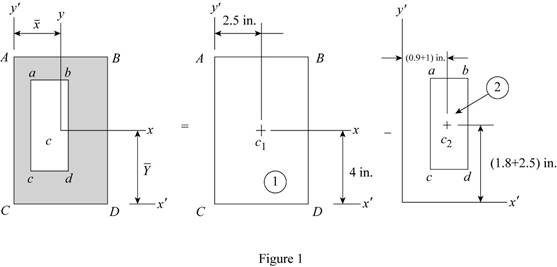
Refer to Figure 1.
Find the area
Substitute
Find the area
Substitute
Find the total area (A) using the relation as follows:
Here,
Substitute
Refer to Figure 1.
Find the centroid
Find the centroid
Find the centroid
Find the centroid
Find the centroid
Substitute
Find the centroid
Substitute
Find the moment of inertia
Substitute
Find the moment of inertia
Substitute
Find the total moment of inertia
Substitute
Thus, the moment of inertia
Find the moment of inertia
Substitute
Find the moment of inertia
Substitute
Find the total moment of inertia
Substitute
Thus, the moment of inertia
Want to see more full solutions like this?
Chapter 9 Solutions
Vector Mechanics for Engineers: Statics and Dynamics


- Correct Answer is written below(preferably handwritten solution) . Detailed and complete fbd only please. I will upvote, thank you.arrow_forwardCurrent Attempt in Progress A cold air-standard Otto cycle has a compression ratio of 9 and the temperature and pressure at the beginning of the compression process are 520°R and 14.2 lbf/in.², respectively. The heat addition per unit mass of air is 600 Btu/lb. Assume constant specific heats evaluted at 520°R. Determine: (a) the maximum temperature, in °R. (b) the maximum pressure, in lbf/in.² (c) the percent thermal efficiency. (d) the mean effective pressure, in lbf/in.²arrow_forwardCorrect Answer is written below(preferably handwritten solution) . Detailed and complete fbd only please. I will upvote, thank you.arrow_forward
- Correct answer and complete detailed fbd only. I will upvote. : The two steel shafts, each with one end builtinto a rigid support, have flanges attached to their freeends. The flanges are to be bolted together. However,initially there is a 6⁰ mismatch in the location of the boltholes as shown in the figure. Determine the maximumshear stress(ksi) in each shaft after the flanges have beenbolted together. The shear modulus of elasticity for steelis 12 x 106 psi. Neglect deformations of the bolts and theflanges.arrow_forwardCorrect detailed answer and complete fbd only. I will upvote. The compound shaft, composed of steel,aluminum, and bronze segments, carries the two torquesshown in the figure. If TC = 250 lb-ft, determine the maximumshear stress developed in each material (in ksi). The moduliof rigidity for steel, aluminum, and bronze are 12 x 106 psi, 4x 10⁶ psi, and 6 x 10⁶ psi, respectivelyarrow_forwardCorrect answer and complete fbd only. I will upvote. A flanged bolt coupling consists of two concentric rows of bolts. The inner row has 6 nos. of 16mm diameterbolts spaced evenly in a circle of 250mm in diameter. The outer row of has 10 nos. of 25 mm diameter bolts spaced evenly in a circle of 500mm in diameter. If the allowable shear stress on one bolt is 60 MPa, determine the torque capacity of the coupling. The Poisson’s ratio of the inner row of bolts is 0.2 while that of the outer row is 0.25 and the bolts are steel, E =200 GPa.arrow_forward
- Correct answer and complete fbd only. I will upvote. The shaft carries a total torque T0 that is uniformly distributedover its length L. Determine the angle of twist (degrees) of the shaft in termsif T0 = 1.2 kN-m, L = 2 m, G = 80 GPa, and diameter = 120 mmarrow_forward7) find the Emax for figure below. 250N Ans: Tmay 7.5 MPa Gomm 350mm 50mm 4arrow_forwardWater is supplied at 150 ft³/s and 70 psi to a hydraulic turbine through a 3-ft inside-diameter inlet pipe as indicated in the figure below. The turbine discharge pipe has a 4.8-ft inside diameter. The static pressure at section (2), 10 ft below the turbine inlet, is 10 in. Hg vacuum. If the turbine develops 2400 hp, determine the rate of loss of available energy between sections (1) and (2). Section (1) P₁ =70psi Q=150ft³/s D₁ = 3 ft 10 ft Turbine power loss = i P₂ = 10 in. Hg vacuum D₂ =4.8ft Section (2) de hparrow_forward
- This problem studies the response of two single degree of freedom bridge systems shown in Figure 1 under three loading cases. The problem has two parts. Part A and Part B use the same loading cases but the system is modified. Assume the following three loading cases in both Part A and Part B: (a) Harmonic wind load acting on the bridge deck pw(t) = powsin(ωwt) with amplitude pow and forcing circular frequency ωw. (b) Harmonic displacement base excitation acting at the base of the bridge pier ug(t) = ugosin(ωgt) with amplitude ugo and displacement circular frequency ωg. (c) Rectangular pulse load acting on the bridge deck with amplitude pop and pulse duration td. Part A The system includes part of a bridge deck and a bridge pier shown in Figure 1(a). For each loading case find the symbolic expression of the peak shear force in the bridge pier assuming the following: • The bridge deck is rigid and it has a mass m. • The bridge deck is rigidly connected with the bridge pier (i.e.,…arrow_forwardspecific speed P #2 Q.2. A Pelton wheel turbine of 1.9 m diameter works under a head of 50 m at 150 rpm. The buckets are exposed to water jet which delivers from a nozzle of 20 cm in diameter. Find the overall efficiency power produced by the wheel if the buckets deflects the jet through an angle of 163°. coefficient of velocity as 0.98 [50 Marks] ·licosply Y and no Take thearrow_forwardd Q.2. A Pelton wheel has a mean bucket speed of 15 m/s. The jet of water issued from a nozzle of 12 cm in diameter impinges the bucket with a velocity of 40 m/s. If the buckets deflect the jet through an angle of 165°, find the head and power generated by the turbine. Assume the hydraulic efficiency is 90% and the mechanical efficiency is 85%. [50 Marks] Po 7n = 90%arrow_forward
 Elements Of ElectromagneticsMechanical EngineeringISBN:9780190698614Author:Sadiku, Matthew N. O.Publisher:Oxford University Press
 Mechanics of Materials (10th Edition)Mechanical EngineeringISBN:9780134319650Author:Russell C. HibbelerPublisher:PEARSON
 Thermodynamics: An Engineering ApproachMechanical EngineeringISBN:9781259822674Author:Yunus A. Cengel Dr., Michael A. BolesPublisher:McGraw-Hill Education
 Control Systems EngineeringMechanical EngineeringISBN:9781118170519Author:Norman S. NisePublisher:WILEY
 Mechanics of Materials (MindTap Course List)Mechanical EngineeringISBN:9781337093347Author:Barry J. Goodno, James M. GerePublisher:Cengage Learning
 Engineering Mechanics: StaticsMechanical EngineeringISBN:9781118807330Author:James L. Meriam, L. G. Kraige, J. N. BoltonPublisher:WILEY