
Videos
Find the moment and product of inertia of the area with respect to x and y axes about through
Answer to Problem 9.192RP
The moment of inertia of the area with respect to x about through
The moment of inertia of the area with respect to y about through
The product of inertia of the area with respect to x and y axes about through
Explanation of Solution
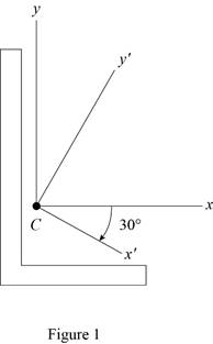
Sketch the cross section as shown in Figure 1.
Refer to Figure 9.13.
The moment of inertia
The moment of inertia
Refer to Problem 9.191.
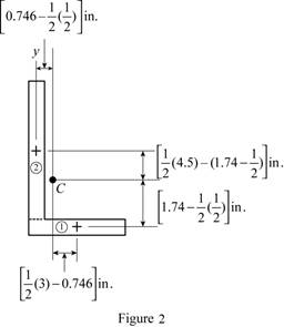
Sketch the cross section as shown in Figure 2.
Express the product of inertia as shown below:
Here,
Applying parallel axis theorem,
When the x and y axis is symmetry.
Refer to Figure 1.
Find the area of semicircle section 1 as shown below:
Here,
Substitute
Find the area of rectangle section 2 as shown below:
Here,
Substitute
Find the centroid for section 1 about x axis
Find the centroid for section 1 about x axis
Find the centroid for section 1 about y axis
Find the centroid for section 2 about x axis
Find the product of inertia of the area with respect to x and y axes by using parallel axis theorem as shown below:
Substitute
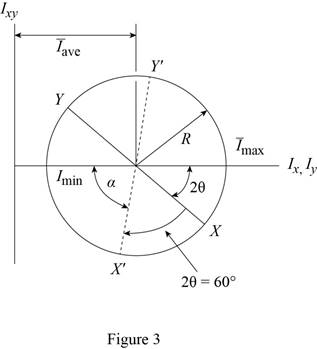
The Mohr circle is defined by the diameter XY, where
Find the average moment of inertia
Here,
Substitute
Find the radius (R) using the relation as shown below:
Here, R is radius and
Substitute
Sketch the Mohr circle as shown in Figure 3.
Refer to Figure 2.
Substitute
Find the angle
Find the moment of inertia of the area with respect to x about through
Here,
Substitute
Thus, the moment of inertia of the area with respect to x about through
Find the moment of inertia of the area with respect to y about through
Substitute
Thus, the moment of inertia of the area with respect to y about through
Find the product of inertia of the area with respect to y about through
Substitute
Thus, the product of inertia of the area with respect to x and y axes about through
(b)
Find the orientation of the principal axes through the centroid and corresponding values.
(b)
Answer to Problem 9.192RP
The orientation of the principal axes at the origin is
The maximum moment of inertia is
The minimum moment of inertia is
Explanation of Solution
Calculation:
Find the orientation of the principal axes through at origin as shown below.
Refer part a.
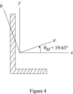
Thus, the orientation of the principal axes at the origin is
Sketch the orientation axis as shown in Figure 4.
Find the maximum moment
Substitute
Thus, the maximum moment of inertia is
Find the minimum moment
Substitute
Thus, the minimum moment of inertia is
Want to see more full solutions like this?
Chapter 9 Solutions
Vector Mechanics for Engineers: Statics and Dynamics


- Box A has a mass of 15 kilograms and is attached to the 20 kilogram Box B using the cord and pulley system shown. The coefficient of kinetic friction between the boxes and surface is 0.2 and the moment of inertia of the pulley is 0.5 kg * m^ 2. After 2 seconds, how far do the boxes move? A бро Barrow_forwardBox A has a mass of 15 kilograms and is attached to the 20 kilogram Box B using the cord and pulley system shown. The coefficient of kinetic friction between the boxes and surface is 0.2 and the moment of inertia of the pulley is 0.5 kg * m^2. Both boxes are 0.25 m long and 0.25 m high. The cord is attached to the bottom of Box A and the middle of box B. After 2 seconds, how far do the boxes move? A From бро Barrow_forwardHomework#8arrow_forwardSign in PDF Lecture W09.pdf PDF MMB241 - Tutorial L9.pdf File C:/Users/KHULEKANI/Desktop/mmb241/MMB241%20-%20Tutorial%20L9.pdf II! Draw | I│Alla | Ask Copilot + of 4 D Topic: Kinetics of Particles: - Forces in dynamic system, Free body diagram, newton's laws of motion, and equations of motion. TQ1. The 10-kg block is subjected to the forces shown. In each case, determine its velocity when t=2s if v 0 when t=0 500 N F = (201) N 300 N (b) TQ2. The 10-kg block is subjected to the forces shown. In each case, determine its velocity at s-8 m if v = 3 m/s at s=0. Motion occurs to the right. 40 N F = (2.5 s) N 200 N 30 N (b) TQ3. Determine the initial acceleration of the 10-kg smooth collar. The spring has an unstretched length of 1 m. 1 σ Q ☆ Q 6 ا الى ☑arrow_forwardSign in PDF Lecture W09.pdf PDF MMB241 - Tutorial L9.pdf File C:/Users/KHULEKANI/Desktop/mmb241/MMB241%20-%20Tutorial%20L9.pdf II! Draw | I│Alla | Ask Copilot + 4 of 4 | D TQ9. If motor M exerts a force of F (10t 2 + 100) N determine the velocity of the 25-kg crate when t kinetic friction between the crate and the plane are μs The crate is initially at rest. on the cable, where t is in seconds, 4s. The coefficients of static and 0.3 and μk = 0.25, respectively. M 3 TQ10. The spring has a stiffness k = 200 N/m and is unstretched when the 25-kg block is at A. Determine the acceleration of the block when s = 0.4 m. The contact surface between the block and the plane is smooth. 0.3 m F= 100 N F= 100 N k = 200 N/m σ Q Q ☆ ا الى 6 ☑arrow_forwardmy ID# is 016948724 please solve this problem step by steparrow_forwardMY ID#016948724 please solve the problem step by spetarrow_forward1 8 4 For the table with 4×4 rows and columns as shown Add numbers so that the sum of any row or column equals .30 Use only these numbers: .1.2.3.4.5.6.10.11.12.12.13.14.14arrow_forwardMY ID# 016948724 please solve this problem step by steparrow_forwardThe pickup truck weighs 3220 Ib and reaches a speed of 30 mi/hr from rest in a distance of 200 ft up the 10-percent incline with constant acceleration. Calculate the normal force under each pair of wheels and the friction force under the rear driving wheels. The effective coefficient of friction between the tires and the road is known to be at least 0.8.arrow_forward1. The figure shows a car jack to support 400kg (W=400kg). In the drawing, the angle (0) varies between 15 and 70 °. The links are machined from AISI 1020 hot-rolled steel bars with a minimum yield strength of 380MPa. Each link consists of two bars, one on each side of the central bearings. The bars are 300mm in length (/) and 25 mm in width (w). The pinned ends have the buckling constant (C) of 1.4 for out of plane buckling. The design factor (nd) is 2.5. (1) Find the thickness (t) of the bars and the factor of safety (n). (2) Check if the bar is an Euler beam. Darrow_forward(Read image)arrow_forwardarrow_back_iosSEE MORE QUESTIONSarrow_forward_ios
 Elements Of ElectromagneticsMechanical EngineeringISBN:9780190698614Author:Sadiku, Matthew N. O.Publisher:Oxford University Press
 Mechanics of Materials (10th Edition)Mechanical EngineeringISBN:9780134319650Author:Russell C. HibbelerPublisher:PEARSON
 Thermodynamics: An Engineering ApproachMechanical EngineeringISBN:9781259822674Author:Yunus A. Cengel Dr., Michael A. BolesPublisher:McGraw-Hill Education
 Control Systems EngineeringMechanical EngineeringISBN:9781118170519Author:Norman S. NisePublisher:WILEY
 Mechanics of Materials (MindTap Course List)Mechanical EngineeringISBN:9781337093347Author:Barry J. Goodno, James M. GerePublisher:Cengage Learning
 Engineering Mechanics: StaticsMechanical EngineeringISBN:9781118807330Author:James L. Meriam, L. G. Kraige, J. N. BoltonPublisher:WILEY