
Statics and Mechanics of Materials Plus Mastering Engineering with Pearson eText - Access Card Package (5th Edition)
5th Edition
ISBN: 9780134301006
Author: Russell C. Hibbeler
Publisher: PEARSON
expand_more
expand_more
format_list_bulleted
Concept explainers
Videos
Textbook Question
Chapter 9.2, Problem 1FP
The 20-mm-diameter A-36 steel rod is subjected to the axial forces shown. Determine the displacement of end C with respect to the fixed support at A.
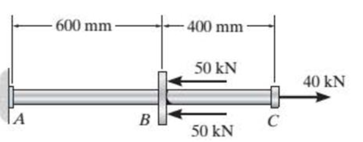
Prob. F9-1.
Expert Solution & Answer
Want to see the full answer?
Check out a sample textbook solution
Students have asked these similar questions
6. Consider a 10N step input to the mechanical system shown below, take M = 15kg, K = 135N/m, and
b = 0.4 Ns/m.
(a) Assume zero initial condition, calculate the
(i)
System pole
(ii)
System characterization, and
(iii) The time domain response
(b) Calculate the steady-state value of the system
b
[
www
K
个
х
M
-F(+)
2. Solve the following linear time invariant differential equations using Laplace transforms subject to
different initial conditions
(a) y-y=t
for y(0) = 1 and y(0) = 1
(b) ÿ+4y+ 4y = u(t)
for y(0) = 0 and y(0) = 1
(c) y-y-2y=0
for y(0) = 1 and y(0) = 0
3. For the mechanical systems shown below, the springs are undeflected when x₁ = x2 = x3 = 0 and
the input is given as fa(t). Draw the free-body diagrams and write the modeling equations governing
each of the systems.
K₁
000
K₂
000
M₁
M2
-fa(t)
B₂
B₁
(a)
fa(t)
M2
K₂
000
B
K₁
x1
000
M₁
(b)
Chapter 9 Solutions
Statics and Mechanics of Materials Plus Mastering Engineering with Pearson eText - Access Card Package (5th Edition)
Ch. 9.2 - In each case, determine the internal normal force...Ch. 9.2 - Determine the internal normal force between...Ch. 9.2 - The post weighs 8 kN/m. Determine the internal...Ch. 9.2 - The rod is subjected to an external axial force of...Ch. 9.2 - The rigid beam supports the load of 60 kN....Ch. 9.2 - The 20-mm-diameter A-36 steel rod is subjected to...Ch. 9.2 - Prob. 2FPCh. 9.2 - The 30-mm-diameter A992 steel rod is subjected to...Ch. 9.2 - Prob. 4FPCh. 9.2 - Prob. 5FP
Ch. 9.2 - The 20-mm-diameter 2014-T6 aluminum rod is...Ch. 9.2 - The A992 steel rod is subjected to the loading...Ch. 9.2 - The copper shaft is subjected to the axial loads...Ch. 9.2 - The composite shaft, consisting of aluminum,...Ch. 9.2 - The composite shaft, consisting of aluminum,...Ch. 9.2 - The 2014-T6 aluminum rod has a diameter of 30 mm...Ch. 9.2 - The A-36 steel drill shaft of an oil well extends...Ch. 9.2 - The truss is made of three A-36 steel members,...Ch. 9.2 - The truss is made of three A-36 steel members,...Ch. 9.2 - The assembly consists of two 10-mm diameter red...Ch. 9.2 - The assembly consists of two 10-mm diameter red...Ch. 9.2 - The load is supported by the four 304 stainless...Ch. 9.2 - The load is supported by the four 304 stainless...Ch. 9.2 - The rigid bur is supported by the pin-connected...Ch. 9.2 - The post is made of Douglas fir and has a diameter...Ch. 9.2 - The post is made of Douglas fir and has a diameter...Ch. 9.2 - The coupling rod is subjected to a force of 5 kip....Ch. 9.2 - Prob. 17PCh. 9.2 - The linkage is made of three pin-connected A992...Ch. 9.2 - The linkage is made of three pin-connected A992...Ch. 9.2 - The assembly consists of three titanium...Ch. 9.2 - The rigid beam is supported at its ends by two...Ch. 9.2 - Prob. 22PCh. 9.2 - The steel bar has the original dimensions shown in...Ch. 9.2 - Determine the relative displacement of one end of...Ch. 9.2 - Prob. 25PCh. 9.2 - The truss consists of three members, each made...Ch. 9.2 - Prob. 27PCh. 9.2 - The observation cage C has a weight of 250 kip and...Ch. 9.2 - Determine the elongation of the aluminum strap...Ch. 9.2 - The ball is truncated at its ends and is used to...Ch. 9.5 - The column is constructed from high-strength...Ch. 9.5 - The column is constructed from high-strength...Ch. 9.5 - The A-36 steel pipe has a 6061-T6 aluminum core....Ch. 9.5 - If column AB is made from high strength precast...Ch. 9.5 - If column AB is made from high strength precast...Ch. 9.5 - Determine the support reactions at the rigid...Ch. 9.5 - If the supports at A and C are flexible and have a...Ch. 9.5 - The load of 2000 lb is to be supported by the two...Ch. 9.5 - The load of 2000 lb is to be supported by the two...Ch. 9.5 - The A-36 steel pipe has an outer radius of 20 mm...Ch. 9.5 - The 10-mm-diameter steel bolt is surrounded by a...Ch. 9.5 - The 10-mm-diametcr steel bolt is surrounded by a...Ch. 9.5 - The assembly consists of two red brass C83400...Ch. 9.5 - The rigid beam is supported by the three suspender...Ch. 9.5 - Prob. 45PCh. 9.5 - If the gap between C and the rigid wall at D is...Ch. 9.5 - The support consists of a solid red brass C83400...Ch. 9.5 - The specimen represents a filament-reinforced...Ch. 9.5 - The rigid bar is pinned at A and supported by two...Ch. 9.5 - The rigid bar is pinned at A and supported by two...Ch. 9.5 - The rigid bar is pinned at A and supported by two...Ch. 9.5 - The rigid bar is pinned at A and supported by two...Ch. 9.5 - The 2014-T6 aluminum rod AC is reinforced with the...Ch. 9.5 - The 2014-T6 aluminum rod AC is reinforced with the...Ch. 9.5 - The three suspender bars are made of A992 steel...Ch. 9.6 - The C83400-red-brass rod AB and 2014-T6-aluminum...Ch. 9.6 - The assembly has the diameters and material...Ch. 9.6 - The rod is made of A992 steel and has a diameter...Ch. 9.6 - The two cylindrical rod segments are fixed to the...Ch. 9.6 - The two cylindrical rod segments are fixed to the...Ch. 9.6 - Prob. 61PCh. 9.6 - The bronze C86100 pipe has an inner radius of 0.5...Ch. 9.6 - The 40-ft-long A-36 steel rails on a train track...Ch. 9.6 - The device is used to measure a change in...Ch. 9.6 - Prob. 65PCh. 9.6 - Prob. 66PCh. 9.6 - Prob. 67PCh. 9.6 - When the temperature is at 30C, the A-36 steel...Ch. 9.6 - The 50-mm-diameter cylinder is made from Am...Ch. 9.6 - The 50-mm-diametcr cylinder is made from Am...Ch. 9.6 - Prob. 71PCh. 9.6 - The cylinder CD of the assembly is heated from T1...Ch. 9.6 - The cylinder CD of the assembly is heated from T1...Ch. 9.6 - Prob. 74PCh. 9 - The assembly consists of two A992 steel bolts AB...Ch. 9 - The assembly shown consists of two A992 steel...Ch. 9 - The rods each have the same 25-mm diameter and...Ch. 9 - Two A992 steel pipes, each having a...Ch. 9 - The 2014-T6 aluminum rod has a diameter of 0.5 in....Ch. 9 - The 2014-T6 aluminum rod has a diameter of 0.5 in....Ch. 9 - The rigid link is supported by a pin at A and two...Ch. 9 - The joint is made from three A992 steel plates...
Knowledge Booster


Learn more about
Need a deep-dive on the concept behind this application? Look no further. Learn more about this topic, mechanical-engineering and related others by exploring similar questions and additional content below.Similar questions
- This question i m uploading second time . before you provide me incorrect answer. read the question carefully and solve accordily.arrow_forward1. Create a table comparing five different analogous variables for translational, rotational, electrical and fluid systems. Include the standard symbols for each variable in their respective systems.arrow_forward2) Suppose that two unequal masses m₁ and m₂ are moving with initial velocities v₁ and v₂, respectively. The masses hit each other and have a coefficient of restitution e. After the impact, mass 1 and 2 head to their respective gaps at angles a and ẞ, respectively. Derive expressions for each of the angles in terms of the initial velocities and the coefficient of restitution. m1 m2 8 m1 m2 βarrow_forward
- 4. Find the equivalent spring constant and equivalent viscous-friction coefficient for the systems shown below. @ B₁ B₂ H B3 (b)arrow_forward5. The cart shown below is inclined 30 degrees with respect to the horizontal. At t=0s, the cart is released from rest (i.e. with no initial velocity). If the air resistance is proportional to the velocity squared. Analytically determine the initial acceleration and final or steady-state velocity of the cart. Take M= 900 kg and b 44.145 Ns²/m². Mg -bx 2 отarrow_forward9₁ A Insulated boundary Insulated boundary dx Let's begin with the strong form for a steady-state one-dimensional heat conduction problem, without convection. d dT + Q = dx dx According to Fourier's law of heat conduction, the heat flux q(x), is dT q(x)=-k dx. x Q is the internal heat source, which heat is generated per unit time per unit volume. q(x) and q(x + dx) are the heat flux conducted into the control volume at x and x + dx, respectively. k is thermal conductivity along the x direction, A is the cross-section area perpendicular to heat flux q(x). T is the temperature, and is the temperature gradient. dT dx 1. Derive the weak form using w(x) as the weight function. 2. Consider the following scenario: a 1D block is 3 m long (L = 3 m), with constant cross-section area A = 1 m². The left free surface of the block (x = 0) is maintained at a constant temperature of 200 °C, and the right surface (x = L = 3m) is insulated. Recall that Neumann boundary conditions are naturally satisfied…arrow_forward
- 1 - Clearly identify the system and its mass and energy exchanges between each system and its surroundings by drawing a box to represent the system boundary, and showing the exchanges by input and output arrows. You may want to search and check the systems on the Internet in case you are not familiar with their operations. A pot with boiling water on a gas stove A domestic electric water heater A motor cycle driven on the roadfrom thermodynamics You just need to draw and put arrows on the first part a b and carrow_forward7. A distributed load w(x) = 4x1/3 acts on the beam AB shown in Figure 7, where x is measured in meters and w is in kN/m. The length of the beam is L = 4 m. Find the moment of the resultant force about the point B. w(x) per unit length L Figure 7 Barrow_forward4. The press in Figure 4 is used to crush a small rock at E. The press comprises three links ABC, CDE and BG, pinned to each other at B and C, and to the ground at D and G. Sketch free-body diagrams of each component and hence determine the force exerted on the rock when a vertical force F = 400 N is applied at A. 210 80 80 C F 200 B 80 E 60% -O-D G All dimensions in mm. Figure 4arrow_forward
- 2. Figure 2 shows a device for lifting bricks and concrete blocks. It comprises two compo- nents ABC and BD, with a frictionless pin at B. Determine the minimum coefficient of friction required at A and D if the device is to work satisfactorily. W all dimensions in inches Figure 2 Darrow_forward1. The shaft AD in Figure 1 supports two pulleys at B and C of radius 200 mm and 250 mm respectively. The shaft is supported in frictionless bearings at A and D and is rotating clockwise (when viewed from the right) at a constant speed of 300 rpm. Only bearing A can support thrust. The tensions T₁ = 200 N, T₂ = 400 N, and T3 = 300 N. The distances AB = 120 mm, BC = 150 mm, and CD120 mm. Find the tension 74 and the reaction forces at the bearings. A T fo Figure 1arrow_forward5. Figure 5 shows a two-dimensional idealization of the front suspension system for a car. During cornering, the road exerts a vertical force of 5 kN and a leftward horizontal force of 1.2 kN on the tire, which is of 510 mm diameter. Draw free-body diagrams of each component and determine the forces transmitted between them. 250 A -320 B 170 D 170 -220-220- all dimensions in mm. Figure 5arrow_forward
arrow_back_ios
SEE MORE QUESTIONS
arrow_forward_ios
Recommended textbooks for you
 International Edition---engineering Mechanics: St...Mechanical EngineeringISBN:9781305501607Author:Andrew Pytel And Jaan KiusalaasPublisher:CENGAGE L
International Edition---engineering Mechanics: St...
Mechanical Engineering
ISBN:9781305501607
Author:Andrew Pytel And Jaan Kiusalaas
Publisher:CENGAGE L
Engineering Basics - Statics & Forces in Equilibrium; Author: Solid Solutions - Professional Design Solutions;https://www.youtube.com/watch?v=dQBvQ2hJZFg;License: Standard YouTube License, CC-BY