
Bundle: Mechanics Of Materials, Loose-leaf Version, 9th + Mindtap Engineering, 2 Terms (12 Months) Printed Access Card
9th Edition
ISBN: 9781337594301
Author: Barry J. Goodno, James M. Gere
Publisher: Cengage Learning
expand_more
expand_more
format_list_bulleted
Concept explainers
Videos
Textbook Question
Chapter 9, Problem 9.5.3P
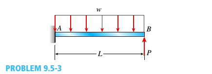
Copper beam AB has circular cross section with a radius of 0.25 in. and length L = 3 ft. The beam is subjected to a uniformly distributed load w = 3.5 lb/ft. Calculate the required load P at joint B so that the total deflection at joint B is zero. Assume that£ = 16,000 ksi.
Expert Solution & Answer

Trending nowThis is a popular solution!

Students have asked these similar questions
Research and select different values for the R ratio from various engine models, then analyze how these changes affect instantaneous velocity and acceleration, presenting your findings visually using graphs.
Qu. 7 The v -t graph of a car while travelling along a road is shown. Draw the s -t and a -t graphs for the motion.
I need to draw a graph and I need to show all work step by step please do not get short cut from dtna
An unpressurized cylindrical tank with a 100-foot diameter holds a 40-foot column of water. What is total force acting against the bottom of the tank?
Chapter 9 Solutions
Bundle: Mechanics Of Materials, Loose-leaf Version, 9th + Mindtap Engineering, 2 Terms (12 Months) Printed Access Card
Ch. 9 - The equation of the deflection curve for a...Ch. 9 - The equation of the deflection curve for a simply...Ch. 9 - -3 The deflection curve for a simple beam AB (see...Ch. 9 - The deflection curve for a simple beam AB (sec...Ch. 9 - The deflection curve for a cantilever beam AB (sec...Ch. 9 - The deflection curve for a cantilever beam AB (see...Ch. 9 - A simply supported beam is loaded with a point...Ch. 9 - A I-meter-long, simply supported copper beam (E =...Ch. 9 - A wide-flange beam (W 12 x 35) supports a uniform...Ch. 9 - A uniformly loaded, steel wide-flange beam with...
Ch. 9 - What is the span length L of a uniformly loaded,...Ch. 9 - -6 Calculate the maximum deflection of a uniformly...Ch. 9 - A cantilever beam with a uniform load (see figure)...Ch. 9 - A gold-alloy microbeam attached to a silicon wafer...Ch. 9 - Obtain a formula for the ratio c/maxof the...Ch. 9 - A cantilever beam model is often used to represent...Ch. 9 - B cams AB and CDE are connected using rigid link...Ch. 9 - -12 Derive the equation of the deflection curve...Ch. 9 - -13 Derive the equation of the deflection curve...Ch. 9 - -14 A cantilever beam AB supporting a triangularly...Ch. 9 - A cantilever beam has a length L = 12 ft and a...Ch. 9 - A simple beam with an overhang is subjected to d...Ch. 9 - -17 A cantilever beam AB is acted upon by a...Ch. 9 - -18 The beam shown in the figure has a sliding...Ch. 9 - -19 Derive the equations of the deflect ion curve...Ch. 9 - -20 Derive the equations of the deflection curve...Ch. 9 - -21 Derive the equations of the deflection curve...Ch. 9 - -22 Derive the equations of the deflection curve...Ch. 9 - -23 The beam shown in the figure has a sliding...Ch. 9 - -1 Derive the equation of the deflection curve for...Ch. 9 - -2 A simple beam AB is subjected to a distrib uted...Ch. 9 - -3 The simple beam AB shown in the figure has...Ch. 9 - -4 A beam with a uniform load has a sliding...Ch. 9 - -5 The distributed load acting on a cantilever...Ch. 9 - -6 A cantilever beam .4B is subjected to a...Ch. 9 - -7 A beam on simple supports is subjected to a...Ch. 9 - Derive the equation of the deflection curve for...Ch. 9 - -9 Derive the equations of the deflection curve...Ch. 9 - -10 Derive the equations of the deflection curve...Ch. 9 - A simply supported beam (E = 1600 ksi) is loaded...Ch. 9 - A simply supported beam (E = 12 GPa) carries a...Ch. 9 - Copper beam AB has circular cross section with a...Ch. 9 - Beam ABC is loaded by a uniform load q and point...Ch. 9 - A cantilever beam of a length L = 2.5 ft has a...Ch. 9 - A cantilever beam carries a trapezoidal...Ch. 9 - -5-7 A cantilever beam AB carries three equalaly...Ch. 9 - A simple beam AB supports five equally spaced...Ch. 9 - The cantilever beam AB shown in the figure has an...Ch. 9 - Beam ACE hangs from two springs, as shown in the...Ch. 9 - What must be the equation y =f(x) of the axis of...Ch. 9 - -12 Determine the angle of rotation Band...Ch. 9 - The cantilever beam ACE shown in the figure has...Ch. 9 - A cantilever beam is subjected to load P at...Ch. 9 - Use the method of superposition to find the angles...Ch. 9 - Repeat Problem 9,5-15 for the anti-symmetric...Ch. 9 - A cantilever beam is subjected to a quadratic...Ch. 9 - A beam ABCD consisting of a simple span BD and an...Ch. 9 - A horizontal load P acts at end C of the bracket...Ch. 9 - A beam ABC having flexural rigidity EI = 75 kN irT...Ch. 9 - Determine the angle of rotation 0Band deflectionCh. 9 - -22 A simple beam AB supports a uniform load of...Ch. 9 - The overhanging beam A BCD supports two...Ch. 9 - A thin metal strip of total weight W and length L...Ch. 9 - An overhanging beam ABC with flexural rigidity EI...Ch. 9 - A beam A BCD rests on simple supports at B and C...Ch. 9 - The compound beam ABC shown in the figure has a...Ch. 9 - A compound beam ABC DE (see figure) consists of...Ch. 9 - A steel beam ABC is simply supported at A and held...Ch. 9 - -30. Calculate the deflection at point C of a beam...Ch. 9 - Compound beam ABC is loaded by point load P = 1.5...Ch. 9 - The compound beam shown in the figure consists of...Ch. 9 - -33 Find the horizontal deflection hand verti cal...Ch. 9 - The fr a me A BCD shown in the heure is squeezed...Ch. 9 - A framework A BCD is acted on by counterclockwise...Ch. 9 - A framework A BCD is acted on by force P at 2L/3...Ch. 9 - A beam ABCDE has simple supports at B and D and...Ch. 9 - A frame ABC is loaded at point C by a force P...Ch. 9 - The wing of a large commercial jet is represented...Ch. 9 - The wing of a small plane is represented by a...Ch. 9 - Find an expression for required moment MA(in terms...Ch. 9 - Find an expression for required moment MA(in terms...Ch. 9 - Find required distance d (in terms of L) so that...Ch. 9 - A cantilever beam has two triangular loads as...Ch. 9 - -1 A cantilever beam AB is subjected to a uniform...Ch. 9 - The load on a cantilever beam AB has a triangular...Ch. 9 - A cantilever beam AB is subjected to a...Ch. 9 - Determine the angle of rotation BBand the...Ch. 9 - -5 Calen1ate the deflections S 3a ndCh. 9 - A cantileverbeam^Cßsupportstwo concentrated loads...Ch. 9 - Obtain formulas for the angle of rotation 0Aat...Ch. 9 - A simple beam AB supports two concentrated loads P...Ch. 9 - A simple beam AB is subjected to a load in the...Ch. 9 - -10 The simple beam AB shown in the figure...Ch. 9 - A simple beam AB is subjected to couples M0and 2A0...Ch. 9 - The cantilever beam ACB shown in the figure has...Ch. 9 - The cantilever beam ACB shown in the figure...Ch. 9 - Beam ACB hangs from two springs, as shown in the...Ch. 9 - -4 A simple beam ABCD has moment of inertia I near...Ch. 9 - A beam ABC has a rigid segment from A to B and a...Ch. 9 - A simple beam ABC has a moment of inertia 1,5 from...Ch. 9 - The tapered cantilever beam AB shown in the figure...Ch. 9 - The tapered cantilever beam AB shown in the figure...Ch. 9 - A tapered cantilever beam A B supports a...Ch. 9 - A tapered cantilever beam AB supports a...Ch. 9 - Repeat Problem 97-10, but now use the tapered...Ch. 9 - A simple beam ACE is constructed with square cross...Ch. 9 - A uniformly loaded simple beam AB (see figure) of...Ch. 9 - A simple beam AB of length L supports a...Ch. 9 - A propped cantilever beam AB of length L and with...Ch. 9 - A simple beam AB of length L is subjected to loads...Ch. 9 - A beam ABC with simple supports at A and B and an...Ch. 9 - A simple beam ACB supporting a uniform load q over...Ch. 9 - The frame shown in the figure consists of a beam...Ch. 9 - A simple beam AB of length L is loaded at the...Ch. 9 - The simple beam shown in the figure supports a...Ch. 9 - An overhanging beam ABC supports a concentrated...Ch. 9 - The cantilever beam shown in the figure supports a...Ch. 9 - A simple beam ACB supports a uniform load of...Ch. 9 - A cantilever beam ACB supports two concentrated...Ch. 9 - The cantilever beam A CB shown in the hgure is...Ch. 9 - The frame A BC support s a concentrated load P at...Ch. 9 - A simple beam ABC DE supports a uniform load of...Ch. 9 - An overhanging beam ABC is subjected to a couple...Ch. 9 - An overhanging beam ABC rests on a simple support...Ch. 9 - A symmetric beam A BCD with overhangs at both ends...Ch. 9 - A heavy object of weight W is dropped onto the...Ch. 9 - An object of weight Wis dropped onto the midpoint...Ch. 9 - A cantilever beam AB of length L = 6 It is...Ch. 9 - A weight W = 20 kN falls through a height h = 1,0...Ch. 9 - A weight W = 4000 lb falls through a height h =...Ch. 9 - An overhanging beam ABC with a rectangular cross...Ch. 9 - A heavy flywheel rotates at an angular speed m...Ch. 9 - A simple beam AB of length L and height /;...Ch. 9 - A cantilever beam JA of length Land height/; (see...Ch. 9 - An overhanging beam ABC of height h has a sliding...Ch. 9 - A simple beam AB of length L and height h (see...Ch. 9 - Beam AB has an elastic support kR at A, pin...
Knowledge Booster


Learn more about
Need a deep-dive on the concept behind this application? Look no further. Learn more about this topic, mechanical-engineering and related others by exploring similar questions and additional content below.Similar questions
- 7. In the following problems check to see if the set S is a vector subspace of the corresponding R. If it is not, explain why not. If it is, then find a basis and the dimension. (a) S = (b) S = {[],+,"} X1 x12x2 = x3 CR³ {[1], 4+4 = 1} CR³ X2arrow_forwardAAA Show laplace transform on 1; (+) to L (y(+)) : SY(s) = x (0) Y(s) = £ [lx (+)] = 5 x(+) · est de 2 -St L [ y (^) ] = So KG) et de D 2 D D AA Y(A) → Y(s) Ŷ (+) → s Y(s) -yarrow_forward1) In each of the following scenarios, based on the plane of impact (shown with an (n, t)) and the motion of mass 1, draw the direction of motion of mass 2 after the impact. Note that in all scenarios, mass 2 is initially at rest. What can you say about the nature of the motion of mass 2 regardless of the scenario? m1 15 <+ m2 2) y "L χ m1 m2 m1 בז m2 Farrow_forward
- 8. In the following check to see if the set S is a vector subspace of the corresponding Rn. If it is not, explain why not. If it is, then find a basis and the dimension. X1 (a) S = X2 {[2], n ≤ n } c X1 X2 CR² X1 (b) S X2 = X3 X4 x1 + x2 x3 = 0arrow_forward2) Suppose that two unequal masses m₁ and m₂ are moving with initial velocities V₁ and V₂, respectively. The masses hit each other and have a coefficient of restitution e. After the impact, mass 1 and 2 head to their respective gaps at angles a and ẞ, respectively. Derive expressions for each of the angles in terms of the initial velocities and the coefficient of restitution. m1 m2 8 m1 ↑ บา m2 ñ Вarrow_forwardThe fallowing question is from a reeds book on applied heat i am studying. Although the answer is provided, im struggling to understand the whole answer and the formulas and the steps theyre using. Also where some ov the values such as Hg and Hf come from in part i for example. Please explain step per step in detail thanks In an NH, refrigerator, the ammonia leaves the evaporatorand enters the cornpressor as dry saturated vapour at 2.68 bar,it leaves the compressor and enters the condenser at 8.57 bar with50" of superheat. it is condensed at constant pressure and leavesthe condenser as saturated liquid. If the rate of flow of the refrigerantthrough the circuit is 0.45 kglmin calculate (i) the compressorpower, (ii) the heat rejected to the condenser cooling water in kJ/s,an (iii) the refrigerating effect in kJ/s. From tables page 12, NH,:2.68 bar, hg= 1430.58.57 bar, hf = 275.1 h supht 50" = 1597.2Mass flow of refrigerant--- - - 0.0075 kgls 60Enthalpy gain per kg of refrigerant in…arrow_forward
- state the formulas for calculating work done by gasarrow_forwardExercises Find the solution of the following Differential Equations 1) y" + y = 3x² 3) "+2y+3y=27x 5) y"+y=6sin(x) 7) y"+4y+4y = 18 cosh(x) 9) (4)-5y"+4y = 10 cos(x) 11) y"+y=x²+x 13) y"-2y+y=e* 15) y+2y"-y'-2y=1-4x³ 2) y"+2y' + y = x² 4) "+y=-30 sin(4x) 6) y"+4y+3y=sin(x)+2 cos(x) 8) y"-2y+2y= 2e* cos(x) 10) y+y-2y=3e* 12) y"-y=e* 14) y"+y+y=x+4x³ +12x² 16) y"-2y+2y=2e* cos(x)arrow_forwardThe state of stress at a point is σ = -4.00 kpsi, σy = 16.00 kpsi, σ = -14.00 kpsi, Try = 11.00 kpsi, Tyz = 8.000 kpsi, and T = -14.00 kpsi. Determine the principal stresses. The principal normal stress σ₁ is determined to be [ The principal normal stress σ2 is determined to be [ The principal normal stress σ3 is determined to be kpsi. kpsi. The principal shear stress 71/2 is determined to be [ The principal shear stress 7½ is determined to be [ The principal shear stress T₁/, is determined to be [ kpsi. kpsi. kpsi. kpsi.arrow_forward
- Repeat Problem 28, except using a shaft that is rotatingand transmitting a torque of 150 N * m from the left bearing to the middle of the shaft. Also, there is a profile keyseat at the middle under the load. (I want to understand this problem)arrow_forwardProb 2. The material distorts into the dashed position shown. Determine the average normal strains &x, Ey and the shear strain Yxy at A, and the average normal strain along line BE. 50 mm B 200 mm 15 mm 30 mm D ΕΙ 50 mm x A 150 mm Farrow_forwardProb 3. The triangular plate is fixed at its base, and its apex A is given a horizontal displacement of 5 mm. Determine the shear strain, Yxy, at A. Prob 4. The triangular plate is fixed at its base, and its apex A is given a horizontal displacement of 5 mm. Determine the average normal strain & along the x axis. Prob 5. The triangular plate is fixed at its base, and its apex A is given a horizontal displacement of 5 mm. Determine the average normal strain &x along the x' axis. x' 45° 800 mm 45° 45% 800 mm 5 mmarrow_forward
arrow_back_ios
SEE MORE QUESTIONS
arrow_forward_ios
Recommended textbooks for you
 Mechanics of Materials (MindTap Course List)Mechanical EngineeringISBN:9781337093347Author:Barry J. Goodno, James M. GerePublisher:Cengage Learning
Mechanics of Materials (MindTap Course List)
Mechanical Engineering
ISBN:9781337093347
Author:Barry J. Goodno, James M. Gere
Publisher:Cengage Learning
Solids: Lesson 53 - Slope and Deflection of Beams Intro; Author: Jeff Hanson;https://www.youtube.com/watch?v=I7lTq68JRmY;License: Standard YouTube License, CC-BY