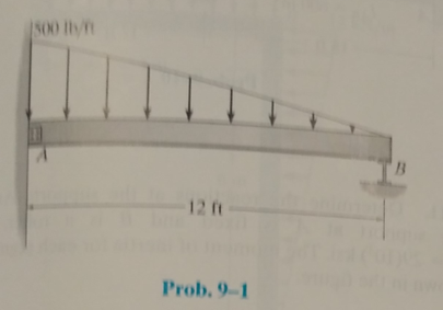
Determine the reactions at the suooorts, then draw the shear and moment diagrams. Assume the support at A is fixed and B is a roller, EI is constant.
The reactions at the supports and to draw the shear and moment diagrams.
Answer to Problem 9.1P
The vertical reaction at support A is
The horizontal reaction at support A is
The reaction moment at support A is
The vertical reaction at support B is
The shear diagram is shown below.

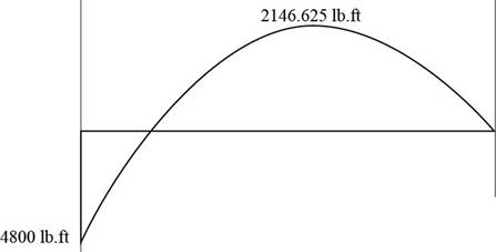
The moment diagram is shown below.
Explanation of Solution
Concept Used:
Write the expression for the net force balance in the vertical direction of the beam.
Here,
Write the expression for the net force balance in the horizontal direction in the beam.
Here,
Write the expression for the net moment about end
Here,
Calculations:
The free body diagram for the beam is shown below.
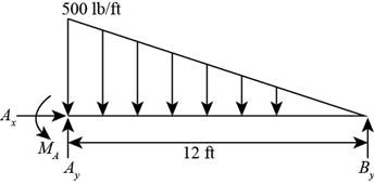
Figure (1)
Here, the vertical reaction at point
Calculate the support reactions using Equation (II).
The uniformly varying load is replaced by a concentrated force of magnitude
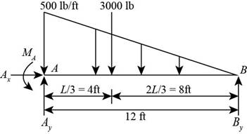
Figure (2)
Consider the moment at point A using Equation (III).
The displacement of the beam for the given load is shown below.
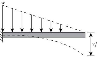
Figure (3)
Calculate the displacement of the beam for the given load.
Here, the displacement of the beam for the given load is
The displacement of the beam for the reaction at point B. is shown below.
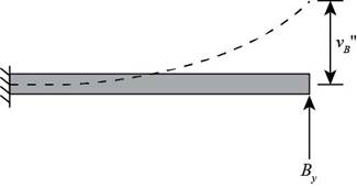
Calculate the displacement of the beam for the given load.
Here, the displacement of the beam for the reaction at point B is
Add Equation (VI) and Equation (VII) for the displacement values according to the compatibility condition.
Substitute
Calculate the vertical reaction at A using Equation (IV).
Substitute
Calculate the bending moment at A using Equation (V).
Substitute
Consider the beam as shown below.
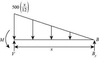
Figure (5)
Write the equation to determine the shear in the beam.
Calculate shear force at a distance
Substitute
Calculate shear force at a distance
Substitute
Calculate shear force at a distance
Substitute
Calculate shear force at a distance
Substitute
Calculate shear force at a distance
Substitute
Substitute
Write the expression for the bending moment.
Calculate moment at a distance
Substitute
Calculate moment at a distance
Substitute
Calculate moment at a distance
Substitute
Calculate moment at a distance
Substitute
Calculate moment at a distance
Substitute
Calculate moment at a distance
Substitute
Conclusion:
The vertical reaction at support A is
The horizontal reaction at support A is
The reaction moment at support A is
The vertical reaction at support B is
The shear diagram is shown below
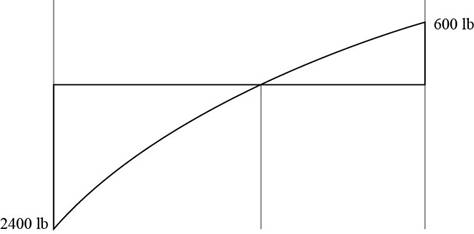
Figure (6)
The moment diagram is shown below

Figure (7)
Want to see more full solutions like this?
Chapter 9 Solutions
Structural Analysis (10th Edition)
Additional Engineering Textbook Solutions
Concepts Of Programming Languages
Starting Out with Python (4th Edition)
Introduction To Programming Using Visual Basic (11th Edition)
Thinking Like an Engineer: An Active Learning Approach (4th Edition)
Java: An Introduction to Problem Solving and Programming (8th Edition)
Modern Database Management

- Find the length of the diagonal on the x-z plane (square root of square of sides). Find angle between the vector F and its projection on x-z (the diagonal defined above). Find Horizontal Projection of F on x-z plane, Fh, and vertical component, FY. Find projections of Fh, to define in-plane components Fx and Fz. Show that results match those of Problem 2(a) above. (2,0,4) F₂ 100 N (5, 1, 1)arrow_forwardFor the control system Draw Nyquist Plot with Solution G(S)= 63.625 (S+1)(S+3) S(S+2)(5+65+18) (5+5)arrow_forwardQ3: Find the support reactions at A: y mm A P=last 2 student's ID#+100 (N) 124N last 3 student's ID# (mm) 724mm 20 mm D B C X last 3 student's ID#+20 mm 744mm 40 mm 60 mmarrow_forward
- A hoist trolley is subjected to the three forces shown. Knowing that α = 40°, determine (a) the required magnitude of the force P if the resultant of the three forces is to be vertical, (b) the corresponding magnißide of the resultant. α 724lb last 3 student's ID# lb α last 2 student's ID#+100 lb 124lb Parrow_forwardFive wood boards are bolted together to form the built-up beam shown in the figure. The beam is subjected to a shear force of V = 13 kips. Each bolt has a shear strength of Vbolt = 6 kips. [h₁ =4.25 in., t₁ = 0.5 in., h₂ = 6 in., t₂ = 1 in.] hi + hi/2 h:/2 h: 2 h + h/2 Determine the moment of inertia of the section. Determine the maximum allowable spacing of the bolts. Determine the shear flow in the section connected by fasteners.arrow_forwardA vessel has a diameter of 1m and 2m high is moving downward with a positive acceleration of 3m/s2. The pressure at the bottom of the liquid is 9.534kPa, determine the mass of the liquid.arrow_forward
- You are the engineer asked to design a rapid sand filtration system for a small water treatment plant. It has the following characteristics: Hydraulic loading rate = 6 m/h Total volumetric flow rate of the plant = 3 MGD Effective filtration rate = 5.8 m/h Production efficiency = 97% Complete (filtration, rinsing, and backwashing) filter cycle duration = 48 h What is the area of your square filtration system? What are the surface dimensions of the filter? What volume of water is needed for backwashing plus rinsing the filter in each rinsing cycle?arrow_forwardFive wood boards are bolted together to form the built-up beam shown in the figure. The beam is subjected to a shear force of V = 14 kips. Each bolt has a shear strength of V bolt = 6 kips. [h₁ = 4 in., t₁ = 0.75 in., h₂ = 6.5 in., t₂ = 1.25 in.] h/2 + hi/2 h:/2 h: 2 hi + hiz Determine the moment of inertia of the section. Calculate the shear force in each bolt. Calculate the shear stress in the bolts.arrow_forwardA box beam is fabricated from two plywood webs that are secured to lumber boards at its top and bottom flanges. The beam supports a concentrated load of P = 4100 lb at the center of a 13-ft span. Bolts (3/8-in. diameter) connect the plywood webs and the lumber flanges at a spacing of s = 9 in. along the span. Supports A and C can be idealized as a pin and a roller, respectively. [w = 4.5 in., b = 0.25 in., t = 5 in., h = 17 in.] B Determine the maximum horizontal shear stress in the plywood webs. Determine the average shear stress in the bolts. Determine the maximum bending stress in the lumber flanges.arrow_forward
- A cantilever flexural member is fabricated by bolting two identical C- section steel shapes back to back as shown in the figure. The beam has a span of L = 1300 mm and supports a concentrated load of P = 800 N. The cross-sectional dimensions of the built- up shape are shown in the figure. Assume the section has a constant thickness of t = 2.5 mm. Bolts of 3.5 mm diameter are installed at intervals of s = 65 mm.[b = 100 mm, a = 25 mm] b T Determine the shear flow in the sections connected by the fasteners. Calculate the shear force in each bolt. Calculate the shear stress in the bolts.arrow_forwardFive wood boards are bolted together to form the built-up beam shown in the figure. The beam is subjected to a shear force of V = 14 kips. Each bolt has a shear strength of V bolt = 6 kips. [h₁4 in., t₁ = 0.75 in., h₂ = 6.5 in., t₂ = 1.25 in.] hi/2 h/2 h2 h:/2 hi/2 + h2 Determine the moment of inertia of the section. Determine the shear flow in the section connected by fasteners. Determine the maximum allowable spacing of the bolts.arrow_forwardTwo built-up beams shown in the figure below have the same dimensions and are connected by the same types of nails with the same spacing. Which beam could carry more shear force if the controlling factor is the shear flow in the fasteners? Nails Beam (1) Z Beam (2) Beam (2) Beam (1) Both are the same Cannot answer without knowing the shear diagram Cannot answer without knowing the modulus of rigidity Nailsarrow_forward

 Steel Design (Activate Learning with these NEW ti...Civil EngineeringISBN:9781337094740Author:Segui, William T.Publisher:Cengage Learning
 Principles of Foundation Engineering (MindTap Cou...Civil EngineeringISBN:9781305081550Author:Braja M. DasPublisher:Cengage Learning
 Residential Construction Academy: House Wiring (M...Civil EngineeringISBN:9781285852225Author:Gregory W FletcherPublisher:Cengage Learning
 Principles of Foundation Engineering (MindTap Cou...Civil EngineeringISBN:9781337705028Author:Braja M. Das, Nagaratnam SivakuganPublisher:Cengage Learning
 Materials Science And Engineering PropertiesCivil EngineeringISBN:9781111988609Author:Charles GilmorePublisher:Cengage Learning