
Concept explainers
Find the reactions and all bar forces for the truss.
Explanation of Solution
Given information:
EI is constant.
The Young’s modulus E of the beam is
The area of all the bars are
Calculation:
Consider the force in the member AC and the horizontal reaction at support B are the redundant.
Remove the redundant to get the released structure.
Sketch the released structure with external loading as shown in Figure 1.
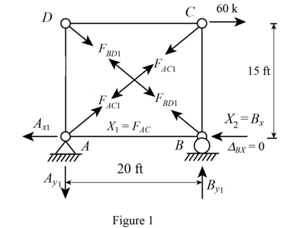
Refer Figure 1.
Consider the force in the member AC as zero.
Find the value of the angle
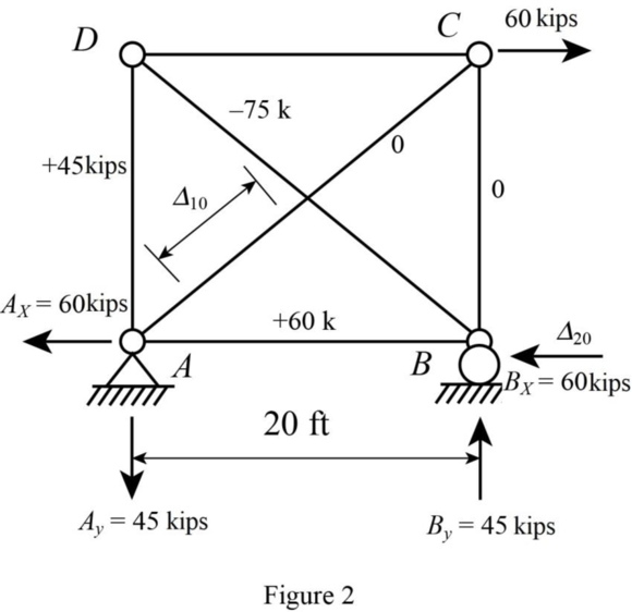
Find the support reaction as follows:
Apply Equation of Equilibrium,
Consider support A.
Apply Equation of Equilibrium,
Consider joint C.
Apply Equation of Equilibrium,
Consider joint D,
Apply Equation of Equilibrium,
Sketch the P system for
Sketch the released structure with unit member force in member AC as shown in Figure 3.
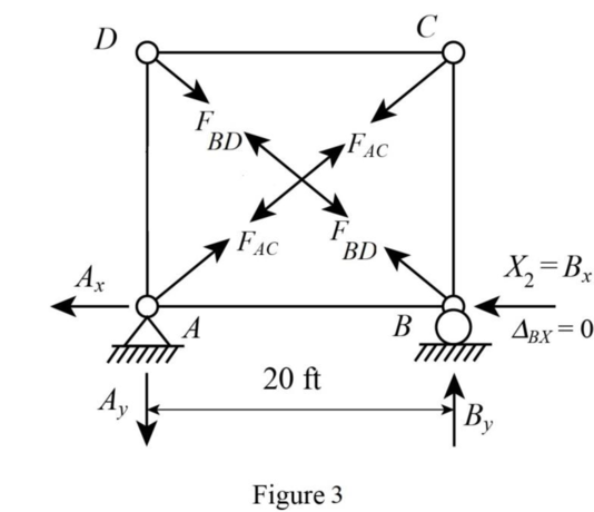
Refer Figure 4.
Consider the force in the member AC is 1 kips.
The support reactions at A and B are zero as no external load acts on the truss.
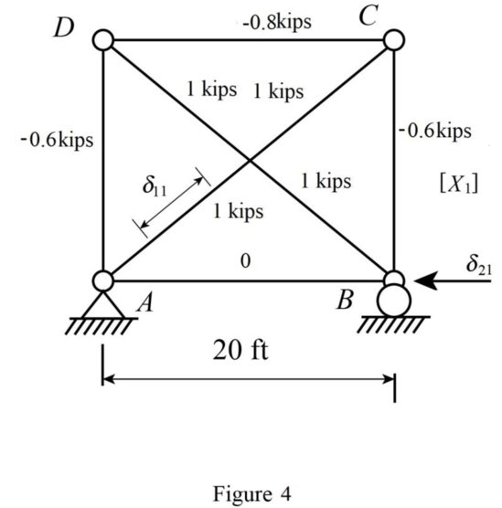
Consider support A.
Apply Equation of Equilibrium,
Consider joint C.
Apply Equation of Equilibrium,
Consider joint D,
Apply Equation of Equilibrium,
Sketch the Q system for
Sketch the Q system for
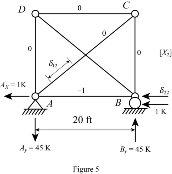
Refer Figure 5.
Find the support reaction at A as follows:
Applying Equation of Equilibrium,
There is no external load at joint D and C and no vertical reaction at A and B.
The force in all the members of the truss except AB is zero.
Consider joint A.
Applying Equation of Equilibrium,
Find the deflection
Find the deflection
Find the deflection
Find the deflection
Find the deflection
Find the deflection
Show the compatibility Equation for
Show the compatibility Equation for
Solve Equation (1) and (2).
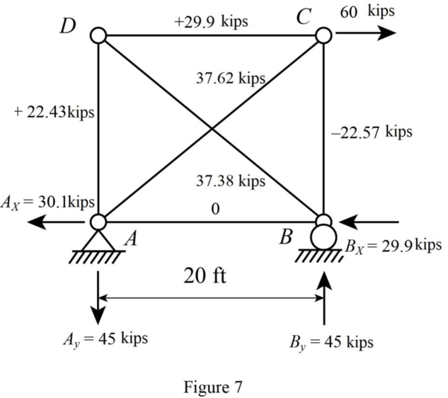
Find the reaction and bar forces in the members of the truss as shown in 6 and 7.
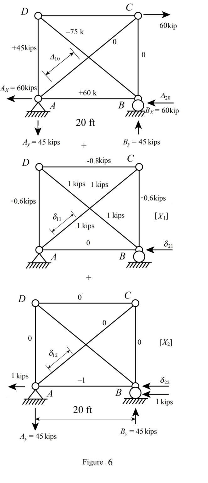
Apply the sum shown in Figure 6 to get the final reactions and member forces shown in Figure 7.
Want to see more full solutions like this?
Chapter 9 Solutions
UCD FUND OF STRUCTURAL ANALYSIS 5E


- For the beam shown, where should a uniformly distributed downward live load, wl, be placed to cause the maximum upward reaction at support A? (D, E, and F are the supports, from left to right, to the right of C.) B C a. From A to B and D to E b. From A to D and E to F c. From B to D and E to F ☑ d. From B to C and D to E L Larrow_forwardQuestion 1 1. A solid shaft of 1.55 m is used as a tractor propeller (prop) shaft. The shaft twists through 1.8 while rotating at 900 rpm. The diameter of the shaft is 60 mm and the modulus of rigidity is 85 GPa. Calculate 1.1 The maximum shear stress in the shaft 1.2 The power transmitted by the shaft. 2. The tractor has undergone minor modifications to increase the transmitted power by 20%. The solid shaft is replaced by a lighter hollow shaft of the same material, with a dimeter ratio of 2:1. Calculate the suitable dimeters of the hollow shaft.arrow_forwardUse Area Moment Method of Beam Deflectionsarrow_forward
- Determine rotations at all the nodes of the beam and reactions at the supports. Assume support 1 and 3 are roller and support 2 is pinned, L1=1.25m, L2=3.75m and w=60kN/m. Please show all working and FBD's where relevant.arrow_forwardspecific gravity of the soil is 1.41 percentage of water content by weight at field capacity and wilting point are 15% and 7% respectively calculate the equivalent moisture content as equivalent depth for 1.2m root zone: A. At permanent wilting point B. At field capacity C. For ready available water Ex 4-3: If the crop consumptive use in Ex(4-2) is 18 m³/donum/day,calculate: A. Irrigation interval in days B. Field water duty assuming 40% losses during irrigation C. Amount of added water to irrigate one donum. n: CFc- IWC) * As *D Lg dn - Q.te A date. A d9 Q IWC- 20% FC-271 Qg-40e D=100cm sec area of the field. Ed=65% 1 hectare As 1.3arrow_forward۰۹:۲۵ ZV9 HW2-C.pdf Dept: Civil Eng. Kerbala HW2 3rd Year (C) Ex 4-1: The field capacity and wilting point as depth equivalent of soil are 178mm and 102 mm respectively. PAD-60% Calculate the irrigation interval if the water consumptive use is 4.5 mm/day. Ex 4-2: The specific gravity of the soil is 1.41 percentage of water content by weight at field capacity and wilting point are 15% and 7% respectively. a) calculate the equivalent depth of moisture content for 1.2m root zone and PAD 70% at permanent wilting point, at field capacity and for readily available water b) If the crop consumptive use is 18 m/donum/day, calculate: Irrigation interval in days, field water duty assuming 40% losses during irrigation and amount of added water to irrigate one hectare. Ex4-3: Using Blaney-Criddle formula, calculate the irrigation interval through specific interval of plant growth according to the following data: . Mean air temperature 25 C percentage of day light hour through the month 8.4% Crop…arrow_forward
- Determine the global stiffness matrix of the beam shown in Fig. 3. Assume supports at 1 and 3 are rollers and the support at 2 is a pinned support. Indicate the degrees of freedom in all the stiffness matrices. EI is constant, w=60kN/m, L1=1.25m and L2=3.75m please explain how the code numbers for global matrix are determined in detailarrow_forwardFor the truss shown in Fig 2, determine the nodal displacement and member forces for all elements of the truss. Assume for each member A = 0.0015 m2 and E = 200 GPa please show all working, relevant FBD's and use ID's indicated in the diagram, if using an alpha numerical in equations please indicate where it is being applied to in the truss.arrow_forwardDetermine the global stiffness matrix of the beam shown in Fig. 3. Assume supports at 1 and 3 are rollers and the support at 2 is a pinned support. Indicate the degrees of freedom in all the stiffness matrices. EI is constant, w=60kN/m, L1=1.25m and L2=3.45m please explain how the code numbers for global matrix are determined in detailarrow_forward

 Structural Analysis (10th Edition)Civil EngineeringISBN:9780134610672Author:Russell C. HibbelerPublisher:PEARSON
 Principles of Foundation Engineering (MindTap Cou...Civil EngineeringISBN:9781337705028Author:Braja M. Das, Nagaratnam SivakuganPublisher:Cengage Learning
 Fundamentals of Structural AnalysisCivil EngineeringISBN:9780073398006Author:Kenneth M. Leet Emeritus, Chia-Ming Uang, Joel LanningPublisher:McGraw-Hill Education
 Traffic and Highway EngineeringCivil EngineeringISBN:9781305156241Author:Garber, Nicholas J.Publisher:Cengage Learning