
Find the maximum negative bending moment at point B.
Answer to Problem 1P
The maximum negative bending moment at point B is
Explanation of Solution
Given Information:
The concentrated live load (P) is 75 kN.
Calculation:
Apply a 1 kN unit moving load at a distance of x from left end A.
Sketch the free body diagram of beam as shown in Figure 1.
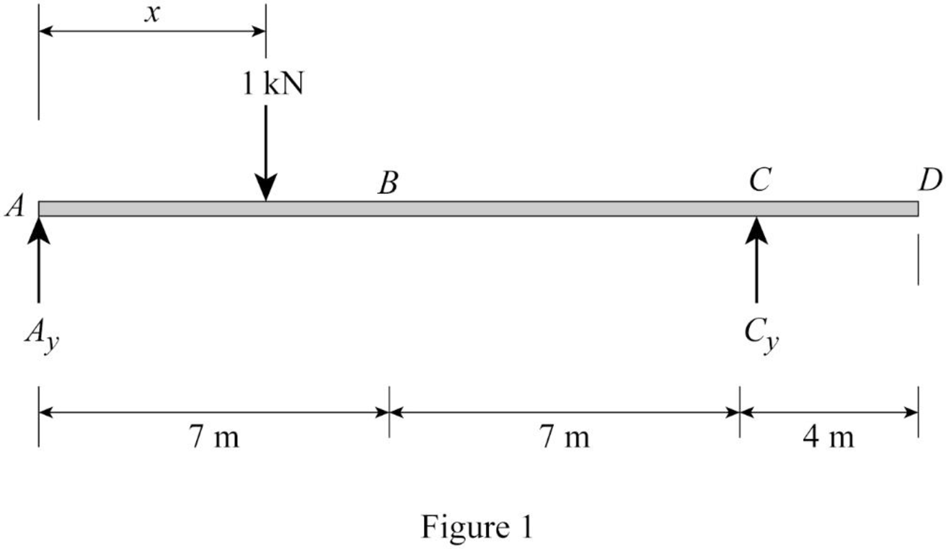
Refer Figure 1.
Find the equation of support reaction
Take moment about point A.
Consider moment equilibrium at point A.
Consider clockwise moment as positive and anticlockwise moment as negative.
Sum of moment at point A is zero.
Find the equation of support reaction
Apply vertical equilibrium equation of forces.
Consider upward force as positive
Substitute
Find the equation of moment at B.
Apply 1 kN at just left of B
Sketch the free body diagram of the section AB as shown in Figure 2.
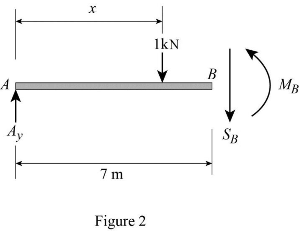
Refer Figure 2.
Consider moment at B.
Consider clockwise moment as positive and anticlockwise moment as negative.
Substitute
Apply 1 kN at just right of B
Sketch the free body diagram of the section BD as shown in Figure 3.
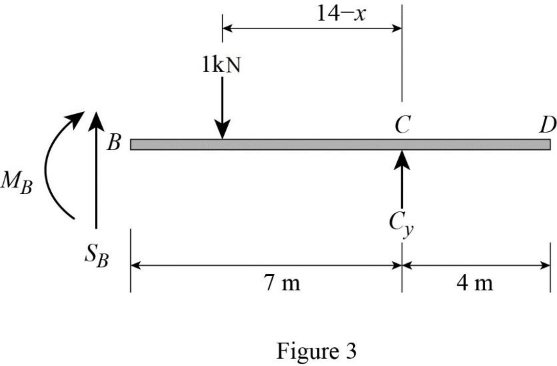
Refer Figure 3.
Consider moment at B.
Consider clockwise moment as positive and anticlockwise moment as negative.
Find the equation of moment at B of portion BC
Substitute
Thus, the equations of the influence line for
Find the value of influence line ordinate of moment at various points of x using the Equations (3) and (4) and summarize the value as in Table 1.
| x | |
| 0 | 0 |
| 7 | |
| 14 | 0 |
| 28 | –2 |
Draw the influence lines for the moment at point B using Table 4 as shown in Figure 4.
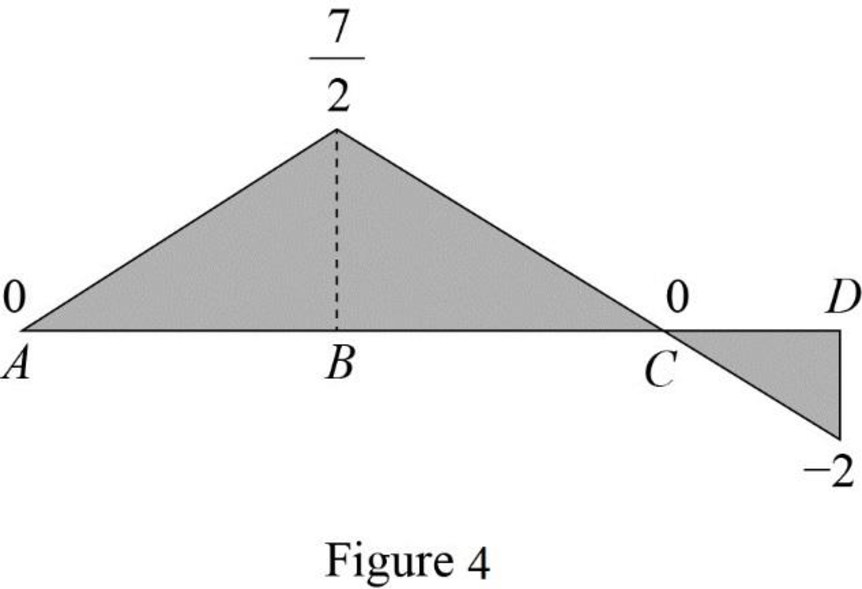
Refer Figure 4,
The maximum negative influence line ordinate of bending moment at B is
Find the maximum negative bending moment at point B using the equation.
Substitute 75 kN for P and
Therefore, the maximum negative bending moment at point B is
Want to see more full solutions like this?
Chapter 9 Solutions
Structural Analysis, SI Edition

- The data needed to answer this question is given in the following link (file is on view only so if you would like to make a copy to make it easier for yourself feel free to do so) https://docs.google.com/spreadsheets/d/1aV5rsxdNjHnkeTkm5VqHzBXZgW-Ptbs3vqwk0SYiQPo/edit?usp=sharingarrow_forwardA k 000 6 ft A kips Bl D ft C C kips 10 ft 12 ft E B k/ft D E ft tarrow_forwardH.W: show that the equations 1. (x+y)dy+(x-y)dx = 0 2. x²dy+(y²-xy)dx = 0 are homogeneous and solve:arrow_forward
- H.W: Solve the differential equation y' - (1+x)(1 + y²) = 0arrow_forwardThe benchmark is 00.00. The backsights are 6.00, 9.32 and 13.75 and 14.00 The foresights are 6.00, 9.00 and 3.22. What is the height of the instrument? H.I. - 100.00 - 124.85 - 43.07- 24.85arrow_forwardThe benchmark is 100.00. The backsights are 4.00, 6.32 and 12.75. The foresights are 6.00, 9.00 and 3.22. What is the elevation of the point? - 95.14 - 123.08 - 104.85 - 81.78arrow_forward
- Determine the stiffness matirx of the entire truss in Global co-ordinate system, clearly indicate the degrees of freedom numbers in the stiffness matrix.arrow_forwardDetermine the stiffness matrices of elements 2, 3 and 4 in the global co-ordinate system. Assume A=0.0015m2 and E=200GPa, indicate the degrees of freedom in all stiffness matricies.arrow_forwardA short plain concrete column with cross-section dimensions of 12 in x 12 in is to be constructed. If the compressive strength of the concrete (f’c) is 5000 psi, what is the maximum load that can be safely applied to the column? - 600 k - 950 k - 720 k - 347 karrow_forward
- The borrow pit has 2000 cyds of suitable fill. The fill required for the project is 1900 cyds. The swell factor is 10% and the shrinkage factor is 15%. How much more borrow do we need? Or is there extra? - 13 yards extra - 13 yards short - 200 yards extra - 161 yards shortarrow_forwardThe job site has a primary vertical control point with a reference benchmark of 100 ft. An instrument is set up with an HI of 5.42 ft above the BM. A grade stake is set at an elevation of 96 ft. What is the height reading on the rod at the grade stake? - 9.42 ft - 4.00 ft - 1.42 ft - 5.42 ftarrow_forwardAssume you have a simple beam 16 ft long supported on each end by R1 and R2. There is a concentrated load of 900 lb that is 4 ft from R2. Reaction R1 is pinned 12 ft from the load. Reaction R1 is 225 lb and R2 is 675 lb. What is the maximum bending moment in pounds per foot? - 3,600 - 1,800 - 2,700- 900arrow_forward
