Find the maximum positive shear and bending moment at point B.
Answer to Problem 13P
The maximum positive shear at point B is
The maximum positive bending moment at point B is
Explanation of Solution
Calculation:
Apply a 1 kN unit moving load at a distance of x from left end A.
Sketch the free body diagram of beam as shown in Figure 1.
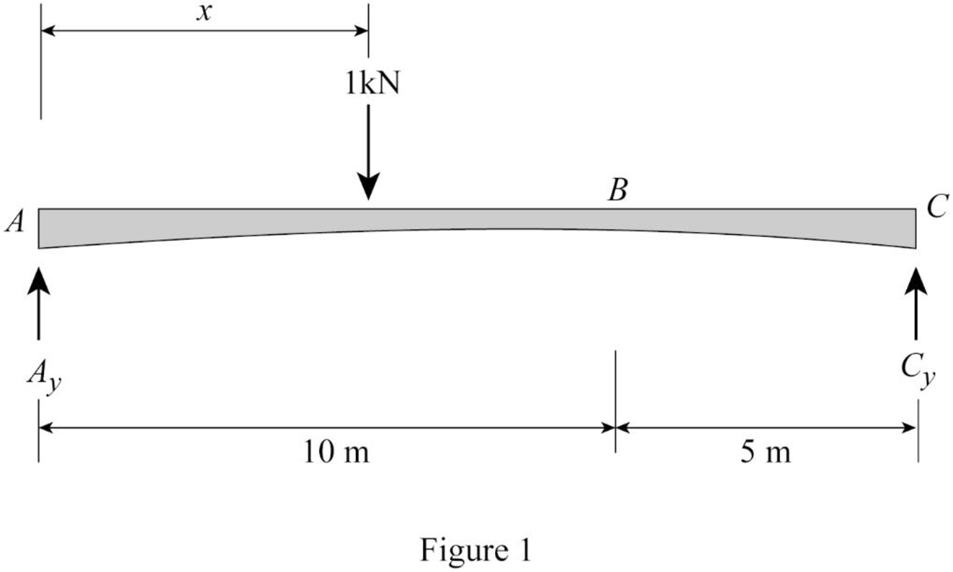
Refer Figure 1.
Find the equation of support reaction
Take moment about point C.
Consider moment equilibrium at point C.
Consider clockwise moment as positive and anticlockwise moment as negative.
Sum of moment at point C is zero.
Find the equation of support reaction
Apply vertical equilibrium equation of forces.
Consider upward force as positive
Substitute
Influence line for shear at point B.
Find the equation of shear force at B of portion AB
Sketch the free body diagram of the section AB as shown in Figure 2.
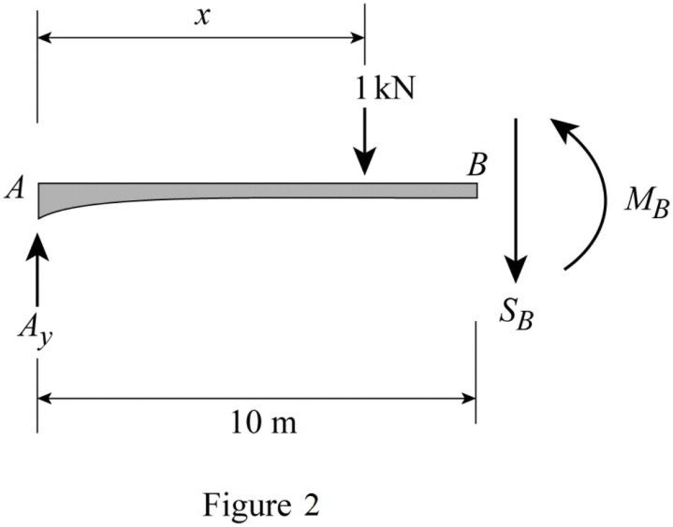
Refer Figure 2.
Apply equilibrium equation of forces.
Consider upward force as positive
Substitute
Find the equation of shear force at B of portion BC
Sketch the free body diagram of the section BC as shown in Figure 3.
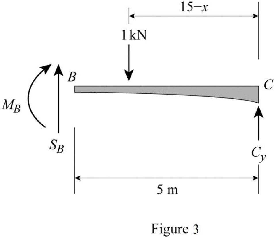
Refer Figure 3.
Apply equilibrium equation of forces.
Consider upward force as positive
Substitute
Thus, the equations of the influence line for
Find the value of influence line ordinate of shear force at various points of x using the Equations (3) and (4) and summarize the value as in Table 1.
| x | |
| 0 | 0 |
| 16 | 0 |
Draw the influence lines for the shear force at point B using Table 1 as shown in Figure 4.
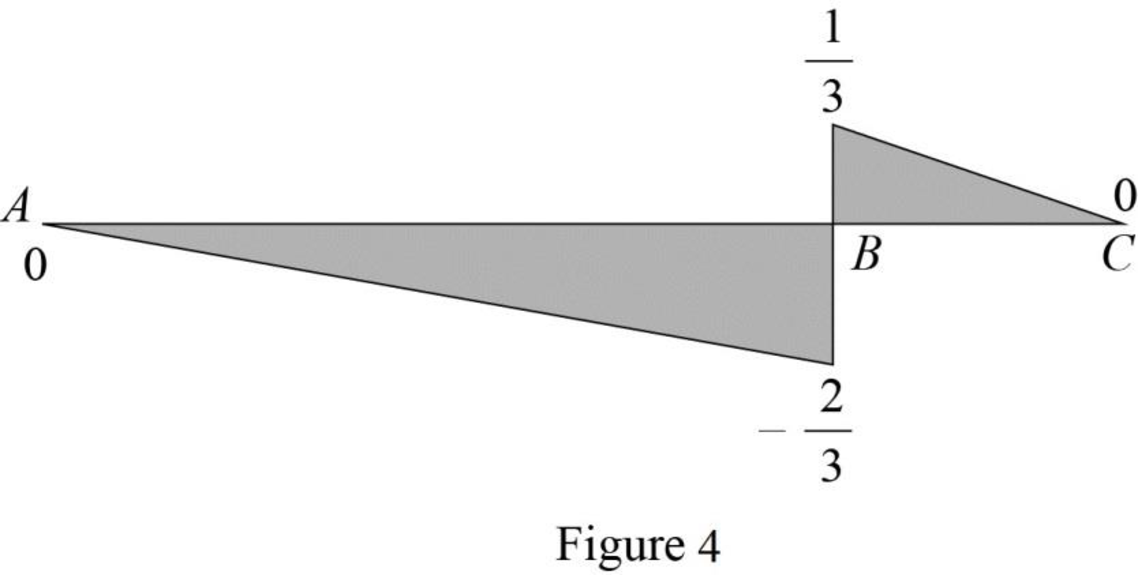
Refer Figure 4.
Find the slope
Here,
Substitute 10 m for
Find the slope
Here,
Substitute 5 m for
Sketch the loading position as shown in Figure 5.
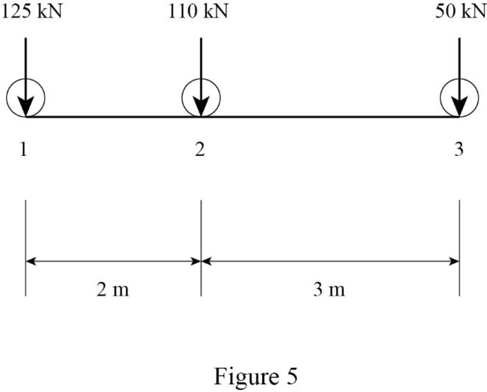
Find the maximum positive shear force at B.
Sketch the loading position on the beam when the load 1 placed at just right of B as shown in Figure 6.
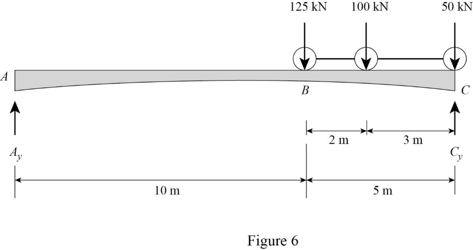
Refer Figure 6.
Find the shear force at B when the load 1 placed at just right of B.
Substitute 5 m for
Sketch the loading position on the beam when the load 2 placed at just right of B as shown in Figure 7.
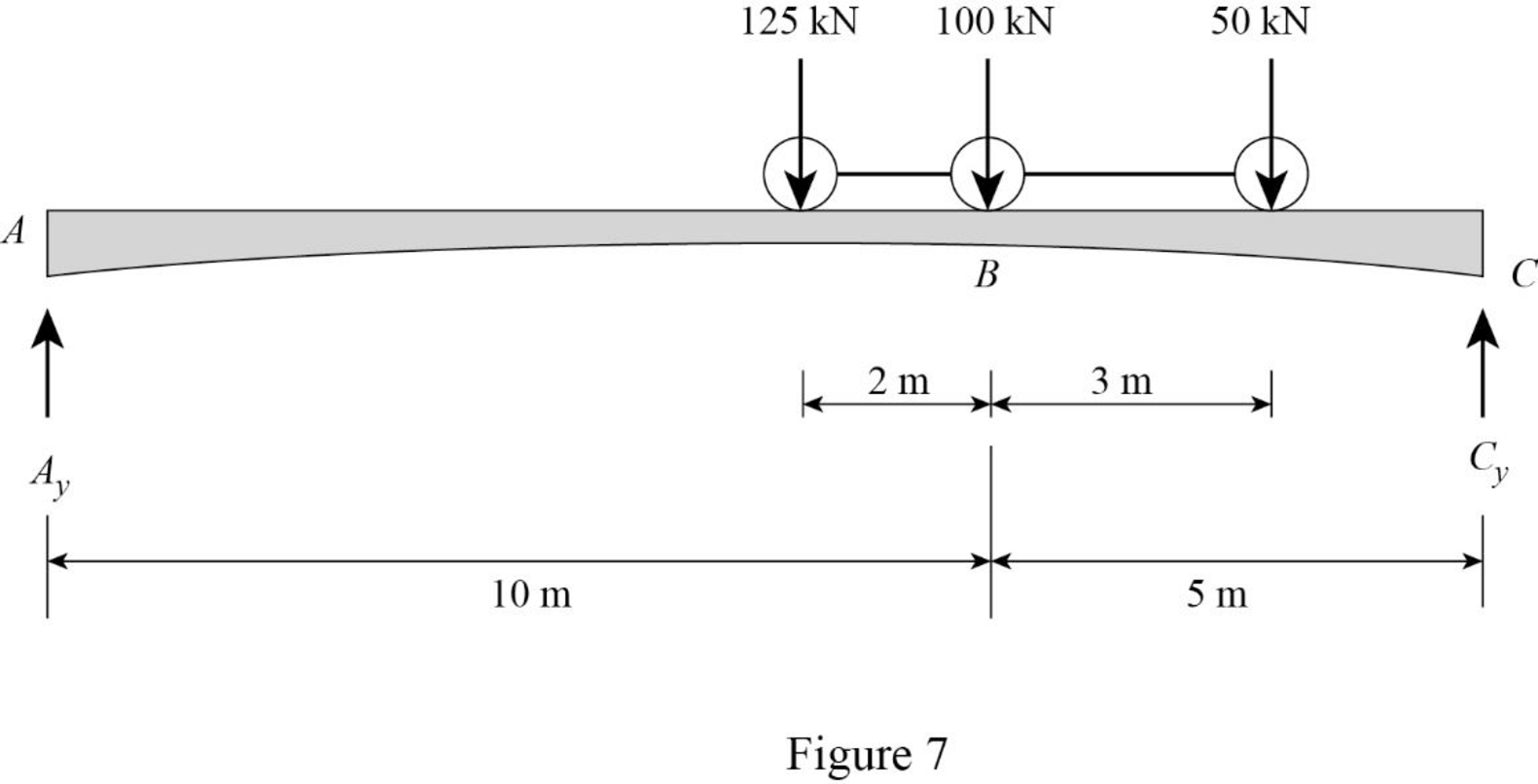
Refer Figure 7.
Find the shear force at B when the load 2 placed at just right of B.
Substitute 10 m for
Sketch the loading position on the beam when the load 3 placed at just right of B as shown in Figure 8.
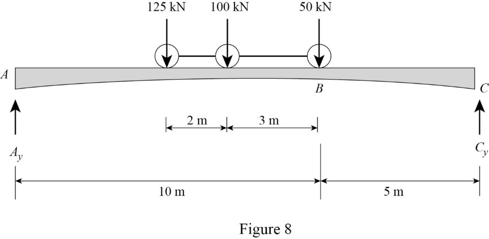
Refer Figure 8.
Find the shear force at B when the load 3 placed at just right of B.
Substitute 10 m for
Maximum positive shear force at B as follows.
The maximum positive shear at B is the maximum of
Therefore, the maximum positive shear at point B is
Influence line for moment at B.
Refer Figure 2.
Consider clockwise moment as positive and anticlockwise moment as negative.
Find the equation of moment at B of portion AB
Substitute
Refer Figure 3.
Consider clockwise moment as negative and anticlockwise moment as positive.
Find the equation of moment at B of portion BC
Substitute
Thus, the equations of the influence line for
Find the value of influence line ordinate of moment at various points of x using the Equations (5) and (6) and summarize the value as in Table 2.
| x | |
| 0 | 0 |
| 10 | |
| 15 | 0 |
Draw the influence lines for the moment at point B using Table 2 as shown in Figure 9.
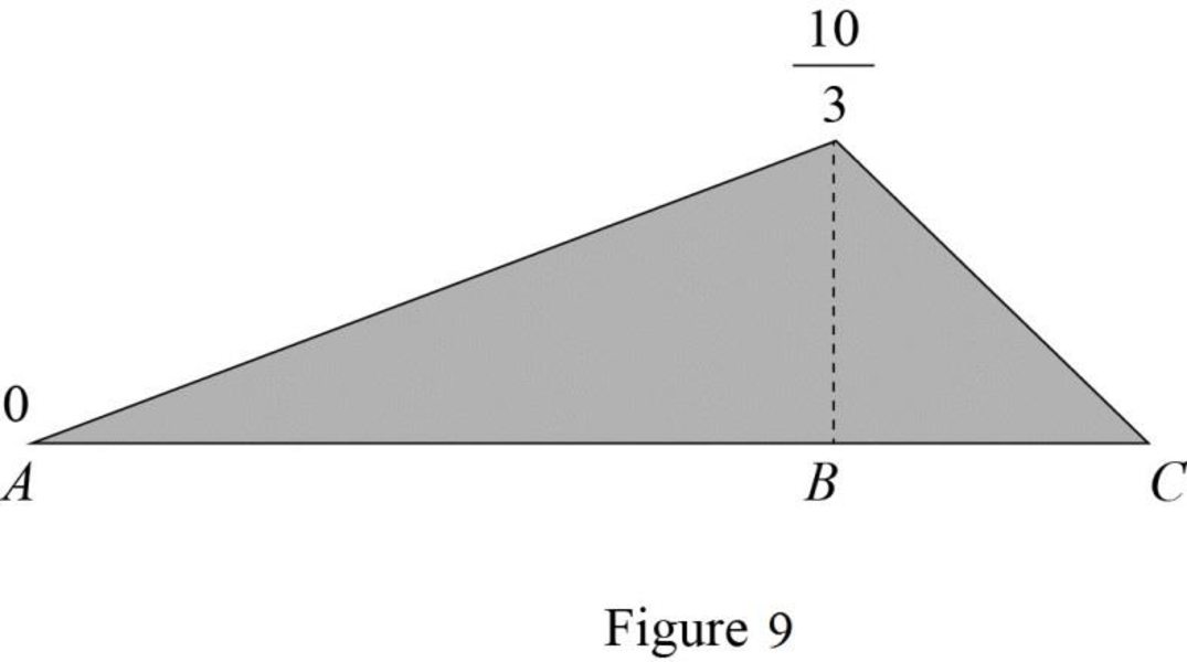
Refer Figure 9.
Find the slope
Here,
Substitute 10 m for
Find the slope
Here,
Substitute 5 m for
Find the maximum positive bending moment at B.
Refer Figure 6.
Find the bending moment at B when the load 1 placed at just right of B.
Substitute 5 m for
Refer Figure 7.
Find the bending moment at B when the load 2 placed at just right of B.
Substitute 10 m for
Refer Figure 8.
Find the bending moment at B when the load 3 placed at just right of B.
Substitute 10 m for
Maximum positive bending moment at B. as follows.
The maximum positive bending moment at B is the maximum of
Therefore, the maximum positive bending moment at point B is
Want to see more full solutions like this?
Chapter 9 Solutions
Structural Analysis, Si Edition

- I need detailed help solving this exercise from homework of Engineering Mathematics II.I do not really understand how to do, please do it step by step, not that long but clear. Thank you!P.S.: Please do not use AI, thanks!arrow_forwardI need detailed help solving this exercise from homework of Engineering Mathematics II.I do not really understand how to do, please do it step by step, not that long but clear. Thank you!P.S.: Please do not use AI, thanks!arrow_forwardI need detailed help solving this exercise from homework of Engineering Mathematics II.I do not really understand how to do, please do it step by step, not that long but clear. Thank you!P.S.: Please do not use AI, thanks!arrow_forward
- I need detailed help solving this exercise from homework of Engineering Mathematics II.I do not really understand how to do, please do it step by step, not that long but clear. Thank you!P.S.: Please do not use AI, thanks!arrow_forwardI need detailed help solving this exercise from homework of Engineering Mathematics II.I do not really understand how to do, please do it step by step, not that long but clear. Thank you!P.S.: Please do not use AI, thanks!arrow_forwardB1.For the truss below, take P₁ = 4 kip and P₂ = 3 kip: a. Determine all member forces. Hint: first find zero-force members (16 pts). b. Use a section cut to verify your answers for members JI, BI, and BC (4 Pts) В 18 ft 6 ft H B 6 ft C 8 ft D p81 8 ft E 8 ft 6 ft F6ftarrow_forward
- Q13: The line CD, C(xc, 6), D(6,yd), the point D is on the right of point C, the value of horizontal effect H(3,0) is on the right of point C, the vertical effect V(0, -2) right of H. the distance between projection of the points H, V is 5cm, Find: 1- The value of xc and yd. 2- The distance between projections of the points C, D. 3- The true length (T.L.) of CD. 4- The angles a and ẞ. 5- A point F in the middle of line CD, find F (xf, yf).arrow_forwardQ9: The straight line AB of true length (8) cm, having the following data: A (5, ya) & B (xb, yb), the point B is on the left of point A, the inclination of the line to the horizontal plane (H.P) is 30° (a) it Horizontal trace H (-3, 0), and point H is on the left of point A with distance (16) cm. Draw the Plan & Elevation of the line AB and determine the following: 1. The missed coordinates: ya, xb, yb. 2. The coordinates of the vertical trace (V). 3. The inclination of the line to the vertical plane (V.P) (B). 4. The distance between projections of the points A and Barrow_forwardQ12: The straight line AB, having the following data: the distance between projections of the points A and B is 8 cm, and A (2.5, 0) & B (0, 6), the point B is on the left of point A. Draw the Plan & Elevation of the line AB and determine the following: 1. The true length T.L of the line AB. 2. The coordinate of Vertical trace V and Horizontal trace H. 3. The inclination of the line to the V.P and H.P. 4. A point E in the middle of the line AB, find E (xe,ye).arrow_forward
- Deformation of a retaining wall is assumed to be as presented in the figure below. Determine:a) variation of the active and passive pressures on the wall for the presented deformation b) magnitude of the total horizontal force on the right side of the wall.arrow_forward2. a) Consider a cable used for aerial tramway (see figure a). The span is 400 m. The unstretched length of the cable is 402 m. Its mass per unit length is 10kg. The elasticity EA = 10 N. Find the horizontal load on the two ends and the sag d. Determine if the small sag condition is satisfied. b) When a cable car whose mass is 500kg is hung below the cable at a horizontal distance of 100 m from the left end, find the horizontal load on the ends. C) As the car goes along the cable, at which position you will see maximum horizontal load on the two ends?arrow_forwardTwo square surface footings are placed 20 feet apart. Calculate ultimate settlements beneath footing I and at the centerline of the two footings.arrow_forward
