Concept explainers
Videos
Compare (a) the systematic design process that leads to a morphological chart with a large number of possible solutions with (b) a design process, in which the problem is identified and then a brainstorming session is started to generate different solutions. Which of these methods would you use. Why? In the event that a certain aspect of the design needs modification, which of the two methods would be easier to apply toward that modification. Why?
The comparison between design process by morphological chart and brainstorming session.
Explanation of Solution
The steps to be followed in the morphological chart are shown below.
- • Extract all purpose functions: The product has to perform these high level functions, they will be near to the root in the function tree. They occupy the first column in the left in the morphological chart.
- • Develop concepts for each function: In this step the aim is to produce as many concepts as possible for the functions that have been identify.
- • For each functions or sub function lists all method that is to be used: In this step, the alternative solution for the problem is listed down. For example to lift the body, you can use different equipment like ladder, screw and rack and pinion arrangement etc.
- • Draw the chart containing possible sub solution: The chart formed in this step is called morphological chart. This chart specifies all possible solution for the given problem.
- • Identify feasible combination: All the solution that has been listed may not feasible, in this step the feasible region is identify.
The figure below shows all possible solution with the feasible solution.
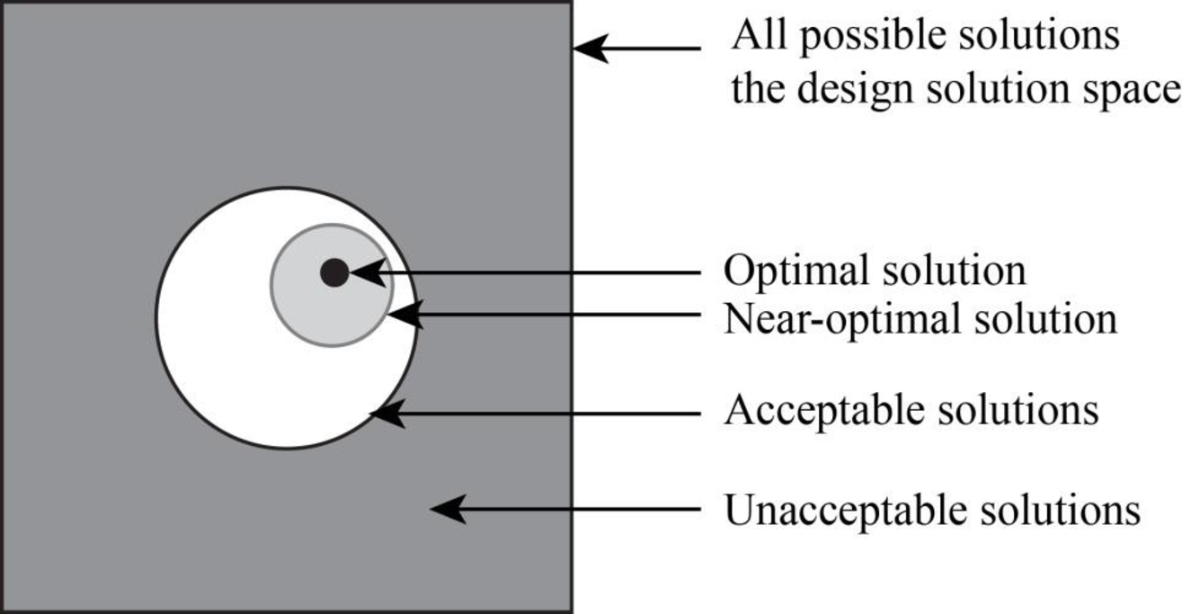
Figure-(1)
Brainstorming:
In this method large number of ideas from the group of people is listed down in the shorter time. The principle is that when there are many ideas, the chance that there will be better idea among them is higher than when there are few ideas.
Some features of the brainstorming is listed down:
- • The leader should clearly state the purpose of the brainstorming session.
- • All participants should tell their solution to the leader.
- • All the ideas are recorded on a flipchart so that all members could see them.
- • After all ideas have been listed, clarify all ideas and eliminate the one which are duplicate.
Both the method can be useful depending upon the situation.
In the event that a certain aspect of the design needs modification brainstorming method would be easier to apply towards that modification because in this method large number of ideas from the group of people is listed down and thereby the best possible outcome can be reached in the shorter time.
Want to see more full solutions like this?
Chapter 8 Solutions
ENGINEERING DESIGN PROCESS


- practise questionarrow_forwardCan you provide steps and an explaination on how the height value to calculate the Pressure at point B is (-5-3.5) and the solution is 86.4kPa.arrow_forwardPROBLEM 3.46 The solid cylindrical rod BC of length L = 600 mm is attached to the rigid lever AB of length a = 380 mm and to the support at C. When a 500 N force P is applied at A, design specifications require that the displacement of A not exceed 25 mm when a 500 N force P is applied at A For the material indicated determine the required diameter of the rod. Aluminium: Tall = 65 MPa, G = 27 GPa. Aarrow_forward
- Find the equivalent mass of the rocker arm assembly with respect to the x coordinate. k₁ mi m2 k₁arrow_forward2. Figure below shows a U-tube manometer open at both ends and containing a column of liquid mercury of length l and specific weight y. Considering a small displacement x of the manometer meniscus from its equilibrium position (or datum), determine the equivalent spring constant associated with the restoring force. Datum Area, Aarrow_forward1. The consequences of a head-on collision of two automobiles can be studied by considering the impact of the automobile on a barrier, as shown in figure below. Construct a mathematical model (i.e., draw the diagram) by considering the masses of the automobile body, engine, transmission, and suspension and the elasticity of the bumpers, radiator, sheet metal body, driveline, and engine mounts.arrow_forward
- 3.) 15.40 – Collar B moves up at constant velocity vB = 1.5 m/s. Rod AB has length = 1.2 m. The incline is at angle = 25°. Compute an expression for the angular velocity of rod AB, ė and the velocity of end A of the rod (✓✓) as a function of v₂,1,0,0. Then compute numerical answers for ȧ & y_ with 0 = 50°.arrow_forward2.) 15.12 The assembly shown consists of the straight rod ABC which passes through and is welded to the grectangular plate DEFH. The assembly rotates about the axis AC with a constant angular velocity of 9 rad/s. Knowing that the motion when viewed from C is counterclockwise, determine the velocity and acceleration of corner F.arrow_forward500 Q3: The attachment shown in Fig.3 is made of 1040 HR. The static force is 30 kN. Specify the weldment (give the pattern, electrode number, type of weld, length of weld, and leg size). Fig. 3 All dimension in mm 30 kN 100 (10 Marks)arrow_forward
- (read image) (answer given)arrow_forwardA cylinder and a disk are used as pulleys, as shown in the figure. Using the data given in the figure, if a body of mass m = 3 kg is released from rest after falling a height h 1.5 m, find: a) The velocity of the body. b) The angular velocity of the disk. c) The number of revolutions the cylinder has made. T₁ F Rd = 0.2 m md = 2 kg T T₂1 Rc = 0.4 m mc = 5 kg ☐ m = 3 kgarrow_forward(read image) (answer given)arrow_forward
 Elements Of ElectromagneticsMechanical EngineeringISBN:9780190698614Author:Sadiku, Matthew N. O.Publisher:Oxford University Press
 Mechanics of Materials (10th Edition)Mechanical EngineeringISBN:9780134319650Author:Russell C. HibbelerPublisher:PEARSON
 Thermodynamics: An Engineering ApproachMechanical EngineeringISBN:9781259822674Author:Yunus A. Cengel Dr., Michael A. BolesPublisher:McGraw-Hill Education
 Control Systems EngineeringMechanical EngineeringISBN:9781118170519Author:Norman S. NisePublisher:WILEY
 Mechanics of Materials (MindTap Course List)Mechanical EngineeringISBN:9781337093347Author:Barry J. Goodno, James M. GerePublisher:Cengage Learning
 Engineering Mechanics: StaticsMechanical EngineeringISBN:9781118807330Author:James L. Meriam, L. G. Kraige, J. N. BoltonPublisher:WILEY