
<LCPO> VECTOR MECH,STAT+DYNAMICS
12th Edition
ISBN: 9781265566296
Author: BEER
Publisher: MCG
expand_more
expand_more
format_list_bulleted
Videos
Textbook Question
Chapter 8.3, Problem 8.77P
A lever of negligible weight is loosely fitted onto a 75-mm-diameter fixed shaft. It is observed that the lever will just start rotating if a 3-kg mass is added at C. Determine the coefficient of static friction between the shaft and the lever.
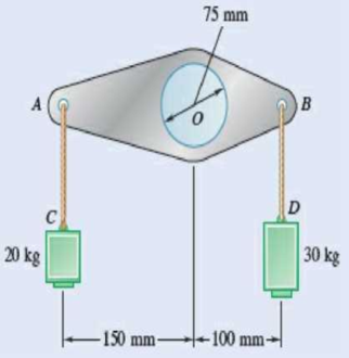
Fig. P8.77
Expert Solution & Answer

Trending nowThis is a popular solution!

Students have asked these similar questions
I REPEAT!!!!! I NEED HANDDRAWING!!!!! NOT A USELESS EXPLANATION!!!! I REPEAT SUBMIT A HANDDRAWING IF YOU CANNOT UNDERSTAND THIS SKIP IT !
I need the real handdrawing complete it by adding these :
Pneumatic Valves
Each linear actuator must be controlled by a directional control valve (DCV) (e.g., 5/2 or 4/2 valve).
The bi-directional motor requires a reversible valve to change rotation direction.
Pressure Regulators & Air Supply
Include two pressure regulators as per the assignment requirement.
Show the main compressed air supply line connecting all components.
Limit Switches & Safety Features
Attach limit switches to each actuator to detect positions.
Implement a two-handed push-button safety system to control actuator movement.
Connections Between Components
Draw air supply lines linking the compressor, valves, and actuators.
Clearly label all inputs and outputs for better understanding.
An elastic bar of the length L and cross section area A is rigidly attached
to the ceiling of a room, and it supports a mass M. Due to the
acceleration of gravity g the rod deforms vertically. The deformation of
the rod is measured by the vertical displacement u(x) governed by the
following equations:
dx
(σ(x)) + b(x) = 0
PDE
σ(x) = Edx
du
Hooke's law
(1)
b(x) = gp=
body force per unit volume
where E is the constant Young's modulus, p is the density, and σ(x) the
axial stress in the rod.
g
* I u(x)
L
2
Chapter 8 Solutions
<LCPO> VECTOR MECH,STAT+DYNAMICS
Ch. 8.1 - Knowing that the coefficient of friction between...Ch. 8.1 - Two blocks A and B are connected by a cable as...Ch. 8.1 - A cord is attached to and partially wound around a...Ch. 8.1 - A 40-kg packing crate must be moved to the left...Ch. 8.1 - Determine whether the block shown is in...Ch. 8.1 - Determine whether the block shown is in...Ch. 8.1 - Determine whether the block shown is in...Ch. 8.1 - Determine whether the block shown is in...Ch. 8.1 - Knowing that = 45 in Prob. 8.1, determine the...Ch. 8.1 - The 20-lb block A hangs from a cable as shown....
Ch. 8.1 - The 10-kg block is attached to link AB and rests...Ch. 8.1 - Considering only values of less than 90,...Ch. 8.1 - Prob. 8.9PCh. 8.1 - Prob. 8.10PCh. 8.1 - The 50-lb block A and the 25-lb block B are...Ch. 8.1 - The 50-lb block A and the 25-lb block B are...Ch. 8.1 - Three 4-kg packages A, B, and C are placed on a...Ch. 8.1 - Prob. 8.14PCh. 8.1 - A uniform crate with a mass of 30 kg must be moved...Ch. 8.1 - A worker slowly moves a 50-kg crate to the left...Ch. 8.1 - Prob. 8.17PCh. 8.1 - A 200-lb sliding door is mounted on a horizontal...Ch. 8.1 - Prob. 8.19PCh. 8.1 - Prob. 8.20PCh. 8.1 - Prob. 8.21PCh. 8.1 - Prob. 8.22PCh. 8.1 - The 10-lb uniform rod AB is held in the position...Ch. 8.1 - Prob. 8.24PCh. 8.1 - Prob. 8.25PCh. 8.1 - Prob. 8.26PCh. 8.1 - The press shown is used to emboss a small seal at...Ch. 8.1 - The machine base shown has a mass of 75 kg and is...Ch. 8.1 - Prob. 8.29PCh. 8.1 - Prob. 8.30PCh. 8.1 - Prob. 8.31PCh. 8.1 - Prob. 8.32PCh. 8.1 - Prob. 8.33PCh. 8.1 - A driver starts the engine of an automobile that...Ch. 8.1 - Prob. 8.35PCh. 8.1 - Two uniform rods each of weight W and length L are...Ch. 8.1 - A 1.2-m plank with a mass of 3 kg rests on two...Ch. 8.1 - Two identical uniform boards, each with a weight...Ch. 8.1 - A uniform 20-kg tube resting on a loading dock...Ch. 8.1 - Prob. 8.40PCh. 8.1 - A 10-ft beam, weighing 1200 lb, is to be moved to...Ch. 8.1 - (a) Show that the beam of Prob. 8.41 cannot be...Ch. 8.1 - Two 8-kg blocks A and B resting on shelves are...Ch. 8.1 - Prob. 8.44PCh. 8.1 - Prob. 8.45PCh. 8.1 - Two slender rods of negligible weight are...Ch. 8.1 - Two slender rods of negligible weight are...Ch. 8.2 - The machine part ABC is supported by a...Ch. 8.2 - Prob. 8.49PCh. 8.2 - Prob. 8.50PCh. 8.2 - Prob. 8.51PCh. 8.2 - Prob. 8.52PCh. 8.2 - Solve Prob. 8.52 assuming that the end of the beam...Ch. 8.2 - Prob. 8.54PCh. 8.2 - Prob. 8.55PCh. 8.2 - Block A supports a pipe column and rests as shown...Ch. 8.2 - A 200-lb block rests as shown on a wedge of...Ch. 8.2 - Prob. 8.58PCh. 8.2 - Prob. 8.59PCh. 8.2 - Prob. 8.60PCh. 8.2 - Prob. 8.61PCh. 8.2 - An 8 wedge is to be forced under a machine base at...Ch. 8.2 - Prob. 8.63PCh. 8.2 - A 15 wedge is forced under a 50-kg pipe as shown....Ch. 8.2 - A 15 wedge is forced under a 50-kg pipe as shown....Ch. 8.2 - Prob. 8.66PCh. 8.2 - Prob. 8.67PCh. 8.2 - Prob. 8.68PCh. 8.2 - Prob. 8.69PCh. 8.2 - Prob. 8.70PCh. 8.2 - Prob. 8.71PCh. 8.2 - The position of the automobile jack shown is...Ch. 8.2 - Prob. 8.73PCh. 8.2 - Prob. 8.74PCh. 8.2 - In the vise shown, the screw is single-threaded in...Ch. 8.2 - Prob. 8.76PCh. 8.3 - A lever of negligible weight is loosely fitted...Ch. 8.3 - Prob. 8.78PCh. 8.3 - 8.79 and 8.80 The double pulley shown is attached...Ch. 8.3 - Prob. 8.80PCh. 8.3 - 8.81 and 8.82 The double pulley shown is attached...Ch. 8.3 - Prob. 8.82PCh. 8.3 - Prob. 8.83PCh. 8.3 - The block and tackle shown are used to lower a...Ch. 8.3 - Prob. 8.85PCh. 8.3 - Prob. 8.86PCh. 8.3 - Prob. 8.87PCh. 8.3 - 8.87 and 8.88 A lever AB of negligible weight is...Ch. 8.3 - Prob. 8.89PCh. 8.3 - Prob. 8.90PCh. 8.3 - Prob. 8.91PCh. 8.3 - Prob. 8.92PCh. 8.3 - Prob. 8.93PCh. 8.3 - Prob. 8.94PCh. 8.3 - Prob. 8.95PCh. 8.3 - Prob. 8.96PCh. 8.3 - Solve Prob. 8.93 assuming that the normal force...Ch. 8.3 - Prob. 8.98PCh. 8.3 - Prob. 8.99PCh. 8.3 - A 900-kg machine base is rolled along a concrete...Ch. 8.3 - Prob. 8.101PCh. 8.3 - Prob. 8.102PCh. 8.4 - A rope having a weight per unit length of 0.4...Ch. 8.4 - A hawser is wrapped two full turns around a...Ch. 8.4 - Two cylinders are connected by a rope that passes...Ch. 8.4 - Prob. 8.106PCh. 8.4 - The coefficient of static friction between block B...Ch. 8.4 - Prob. 8.108PCh. 8.4 - A band belt is used to control the speed of a...Ch. 8.4 - Prob. 8.110PCh. 8.4 - The setup shown is used to measure the output of a...Ch. 8.4 - A flat belt is used to transmit a couple from drum...Ch. 8.4 - Prob. 8.113PCh. 8.4 - Prob. 8.114PCh. 8.4 - The speed of the brake drum shown is controlled by...Ch. 8.4 - The speed of the brake drum shown is controlled by...Ch. 8.4 - Prob. 8.117PCh. 8.4 - Bucket A and block C are connected by a cable that...Ch. 8.4 - Prob. 8.119PCh. 8.4 - Prob. 8.120PCh. 8.4 - 8.121 and 8.123 A cable is placed around three...Ch. 8.4 - Prob. 8.122PCh. 8.4 - Prob. 8.123PCh. 8.4 - Prob. 8.124PCh. 8.4 - Prob. 8.125PCh. 8.4 - Prob. 8.126PCh. 8.4 - The axle of the pulley is frozen and cannot rotate...Ch. 8.4 - The 10-lb bar AE is suspended by a cable that...Ch. 8.4 - Prob. 8.129PCh. 8.4 - Prove that Eqs. (8.13) and (8.14) are valid for...Ch. 8.4 - Complete the derivation of Eq. (8.15), which...Ch. 8.4 - Prob. 8.132PCh. 8.4 - Solve Prob. 8.113 assuming that the flat belt and...Ch. 8 - 8.134 and 8.135 The coefficients of friction are S...Ch. 8 - Prob. 8.135RPCh. 8 - Prob. 8.136RPCh. 8 - A slender rod with a length of L is lodged between...Ch. 8 - The hydraulic cylinder shown exerts a force of 3...Ch. 8 - Prob. 8.139RPCh. 8 - Bar AB is attached to collars that can slide on...Ch. 8 - Two 10 wedges of negligible weight are used to...Ch. 8 - A 10 wedge is used to split a section of a log....Ch. 8 - Prob. 8.143RPCh. 8 - A lever of negligible weight is loosely fitted...Ch. 8 - In the pivoted motor mount shown, the weight W of...
Knowledge Booster


Learn more about
Need a deep-dive on the concept behind this application? Look no further. Learn more about this topic, mechanical-engineering and related others by exploring similar questions and additional content below.Similar questions
- An elastic bar of the length L and cross section area A is rigidly attached to the ceiling of a room, and it supports a mass M. Due to the acceleration of gravity g the rod deforms vertically. The deformation of the rod is measured by the vertical displacement u(x) governed by the following equations: dx (σ(x)) + b(x) = 0 PDE σ(x) = Edx du Hooke's law (1) b(x) = gp= body force per unit volume where E is the constant Young's modulus, p is the density, and σ(x) the axial stress in the rod. g * I u(x) L 2arrow_forwardمتوسعة الفرج بو عمامة المستوى رم الواجب المنزلي رقم 04 تمرین الوان حسب يتمعن العبارات الأتية : A= (+2)+(-45) B=(+13)- C = (+17)-(+13)-(-20)+(-19 D= [(-15)-(+15)]-[(+20) + هست قیم مدرج مبدؤه النقطة ة الطول :tcm A(-2,5): B(+ 2,5) ≤ C (+5) المسافتين : BAD ين الثاني لمستوي مبدؤه 8 وحدتهarrow_forwardPlease do not rely too much on AI, because its answer may be wrong. Please consider it carefully and give your own answer!!!!! You can borrow ideas from AI, but please do not believe its answer.Very very grateful! ( If you write by hand or don't use AI, I'll give you a big thumbs up ) Please do not copy other's work,i will be very very grateful!!Please do not copy other's work,i will be very very grateful!!arrow_forward
- A thin uniform rod of mass m and length 2r rests in a smooth hemispherical bowl of radius r. A moment M = mgr horizontal plane. is applied to the rod. Assume that the bowl is fixed and its rim is in the HINT: It will help you to find the length l of that portion of the rod that remains outside the bowl. M 2r Ꮎ a) How many degrees of freedom does this system have? b) Write an equation for the virtual work in terms of the angle 0 and the motion of the center of mass (TF) c) Derive an equation for the variation in the position of the center of mass (i.e., Sŕƒ) a. HINT: Use the center of the bowl as the coordinate system origin for the problem. d) In the case of no applied moment (i.e., M = 0), derive an equation that can be used to solve for the equilibrium angle of the rod. DO NOT solve the equation e) In the case of an applied moment (i.e., M: = mgr 4 -) derive an equation that can be used to solve for the equilibrium angle of the rod. DO NOT solve the equation. f) Can the angle 0 and…arrow_forwardSolve this problem and show all of the workarrow_forwardSolve this problem and show all of the workarrow_forward
- Solve this problem and show all of the workarrow_forwardPlease do not rely too much on chatgpt, because its answer may be wrong. Please consider it carefully and give your own answer. You can borrow ideas from gpt, but please do not believe its answer.Very very grateful! Please do not copy other's work,i will be very very grateful!!Please do not copy other's work,i will be very very grateful!!arrow_forward= The frame shown is fitted with three 50 cm diameter frictionless pulleys. A force of F = 630 N is applied to the rope at an angle ◊ 43°. Member ABCD is attached to the wall by a fixed support at A. Find the forces indicated below. Note: The rope is tangent to the pully (D) and not secured at the 3 o'clock position. a b •C *су G E e d BY NC SA 2013 Michael Swanbom Values for dimensions on the figure are given in the following table. Note the figure may not be to scale. Variable Value a 81 cm b 50 cm с 59 cm d 155 cm For all answers, take x as positive to the right and positive upward. At point A, the fixed support exerts a force of: A = + ĴN and a reaction couple of: →> ΜΑ Member CG is in Select an answer magnitude У as k N-m. and carries a force of N.arrow_forward
- The lower jaw AB [Purple 1] and the upper jaw-handle AD [Yellow 2] exert vertical clamping forces on the object at R. The hand squeezes the upper jaw-handle AD [2] and the lower handle BC [Orane 4] with forces F. (Member CD [Red 3] acts as if it is pinned at D, but, in a real vise-grips, its position is actually adjustable.) The clamping force, R, depends on the geometry and on the squeezing force F applied to the handles. Determine the proportionality between the clamping force, R, and the squeezing force F for the dimensions given. d3 d4 R 1 B d1 2 d2 D... d5 F 4 F Values for dimensions on the figure are given in the following table. Note the figure may not be to scale. Variable Value d1 65 mm d2 156 mm d3 50 mm 45 d4 d5 113 mm 30 mm R = Farrow_forwardA triangular distributed load of max intensity w =460 N/m acts on beam AB. The beam is supported by a pin at A and member CD, which is connected by pins at C and D respectively. Determine the reaction forces at A and C. Enter your answers in Cartesian components. Assume the masses of both beam AB and member CD are negligible. cc 040 BY NC SA 2016 Eric Davishahl W A C D -a- B Ул -b- x Values for dimensions on the figure are given in the following table. Note the figure may not be to scale. Variable Value α 5.4 m b 8.64 m C 3.24 m The reaction at A is A = i+ ĴN. λ = i+ Ĵ N. The reaction at C is C =arrow_forward56 Clamps like the one shown are commonly used in woodworking applications. This clamp has the dimensions given in the table below the figure, and its jaws are mm thick (in the direction perpendicular to the plane of the picture). a.) The screws of the clamp are adjusted so that there is a uniform pressure of P = 150 kPa being applied to the workpieces by the jaws. Determine the force carried in each screw. Hint: the uniform pressure can be modeled in 2-D as a uniform distributed load with intensity w = Pt (units of N/m) acting over the length of contact between the jaw and the workpiece. b.) Determine the minimum vertical force (parallel to the jaws) required to pull either one of the workpieces out of the clamp jaws. Use a coefficient of static friction between all contacting surfaces of μs = 0.56 and the same clamping pressure given for part (a). 2013 Michael Swanbom A B C a Values for dimensions on the figure are given in the following table. Note the figure may not be to scale.…arrow_forward
arrow_back_ios
SEE MORE QUESTIONS
arrow_forward_ios
Recommended textbooks for you
 International Edition---engineering Mechanics: St...Mechanical EngineeringISBN:9781305501607Author:Andrew Pytel And Jaan KiusalaasPublisher:CENGAGE L
International Edition---engineering Mechanics: St...
Mechanical Engineering
ISBN:9781305501607
Author:Andrew Pytel And Jaan Kiusalaas
Publisher:CENGAGE L
How to balance a see saw using moments example problem; Author: Engineer4Free;https://www.youtube.com/watch?v=d7tX37j-iHU;License: Standard Youtube License