
Concept explainers
Videos
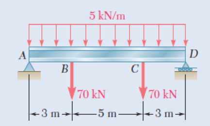
8.9 through 8.14 Each of the following problems refers to a rolled-steel shape selected in a problem of Chap. 5 to support a given loading at a minimal cost while satisfying the requirement σm ≤ σall. For the selected design, determine (a) the actual value of σm in the beam, (b) the maximum value of the principal stress σmax at the junction of a flange and the web.
8.9 Loading of Prob. 5.73 and selected W530 × 92 shape.
Fig. P5.73
(a)
The actual value of σm in the beam.
Answer to Problem 9P
The actual value of σm in the beam is 137.5 MPa_.
Explanation of Solution
Given information:
Refer to problem 5.73 in chapter 5 in the textbook.
The shape of the rolled steel section is W530×92.
Calculation:
Show the free-body diagram of the beam as in Figure 1.
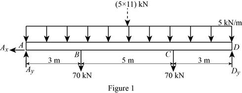
Determine the vertical reaction at point D by taking moment at point A.
∑MA=0−70(3)−(5×11)×112−70(8)+Dy(11)=0−210−302.5−560+11Dy=0Dy=97.5 kN
Determine the vertical reaction at point A by resolving the vertical component of forces.
∑Fy=0Ay−70−70−(5×11)+Dy=0Ay−140−55+97.5=0Ay=97.5 kN
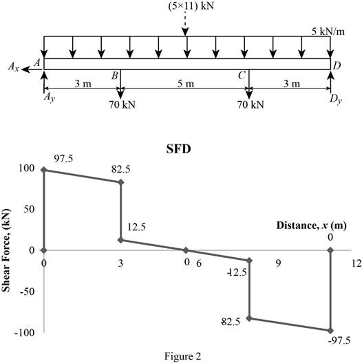
Shear force:
Show the calculation of shear force as follows;
VA=97.5 kN
VB−VA=−5×3VLeftB=−15+VA=−15+97.5=82.5 kN
VRightB=82.5−70=12.5 kN
VC−VB=−5×5−70VLeftC=−95+VB=−95+82.5=−12.5 kN
VRightC=−12.5−70=−82.5 kN
VD−VC=−5×3−70VD=−15−70+VC=−85−12.5=−97.5 kN
Show the calculated shear force values as in Table 1.
| Location (x) m | Shear force (V) kN |
| A | 97.5 |
| B (Left) | 82.5 |
| B (Right) | 12.5 |
| C (Left) | –12.5 |
| C (Right) | –82.5 |
| D | –97.5 |
Plot the shear force diagram as in Figure 2.
Location of the maximum bending moment:
The maximum bending moment occurs where the shear force changes sign.
Refer to Figure 2;
Use the method of similar triangle.
12.5x=12.55−x62.5−12.5x=12.5x25x=62.5x=2.5 m
The maximum bending moment occurs at a distance 5.5 m from the left end of the beam.
Bending moment:
Show the calculation of the bending moment as follows;
MA=0
MB−MA=(82.5×3)+12×(97.5−82.5)×3MB=247.5+22.5+MA=270+0=270 kN-m
Mmax−MB=12×12.5×2.5Mmax=15.625+MB=15.625+270=285.625 kN-m
MC−Mmax=−12×12.5×2.5MC=−15.625+Mmax=−15.625+285.625=270 kN-m
MD=0
Show the calculated bending moment values as in Table 2.
| Location (x) m | Bending moment (M) kN-m |
| A | 0 |
| B | 270 |
| Max BM | 285.625 |
| C | 270 |
| D | 0 |
Plot the bending moment diagram as in Figure 3.
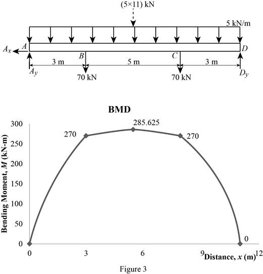
Refer to the Figure 3;
The maximum bending moment in the beam is |Mmax|=285.625 kN-m.
Write the section a property for a W530×92 rolled steel section as table 2.
| Dimension | Unit( mm) |
| d | 533 mm |
| bf | 209 mm |
| tf | 15.6 mm |
| tw | 10.2 mm |
| I | 554×106 mm4 |
| S | 2080×103 mm3 |
Here, d is depth of the section, bf is breadth of the flange, tf is thickness of the flange, Ix is moment of inertia about x-axis, and S is section modulus.
Find the value of C using the relation:
c=12d (1)
Substitute 533 mm for d in Equation (1).
c=12×533=266.5 mm
Find the maximum value of normal stress (σm) in the beam using the relation:
σm=|M|maxS (2)
Here, |M|max is maximum bending moment and S is the section modulus.
Substitute 285.625 kN-m for |M|max and 2080×103 mm3 for S in Equation (2).
σm=285.625 kN-m(103 N-mkN-m)2080×103 mm3(10−9 m31 mm3) =285.625×1032.08×10−3=137,319,711.5 Pa(1 Mpa106 Pa)
σm=137.5 Pa
Thus, the actual value of σm in the beam is 137.5 MPa_.
(b)
The maximum value of principal stress σmax at the junction of a flange and the web.
Answer to Problem 9P
The maximum value of principal stress σmax at the junction of a flange and the web is 129.5 MPa_.
Explanation of Solution
Calculation:
Find the value yb as follows:
yb=c−tf (3)
Here, c is the centroid and tf is the thickness of flange.
Substitute 266.5 mm for c and 15.6 mm for tf in Equation (3).
yb=266.5−15.6=250.9 mm
Find the area of flange (Af) of section using the relation:
Af=bftf (4)
Here, bf is the width of the flange and tf is the thickness of the flange.
Substitute 209 mm For bf and 15.6 mm for tf in Equation (4).
Af=209×15.6=3,260.4 mm2
Find the centroid of flange ˉy using the relation:
ˉy=12(c+yb) (5)
Substitute 266.5 mm for c and 250.9 mm for yb in Equation (5).
ˉy=12(266.5 +250.9)=258.7mm
Find the first moment about neutral axis (Q) as follows:
(Q)=Afˉy (6)
Here, Af is the area of flange and ˉy is the centroid.
Substitute 3,260.4 mm2 for Af and 258.7mm for ˉy in Equation (6).
(Q)=3,260.4 ×258.7=843.47×103 mm3
At mid span the value of V=0 and τb=0.
Find the maximum value of principal stress σmax as follows:
σb=ybcσm (7)
Here, actual value of normal stress yb is distance between centroid of the section to the centre of flange and c is the centroid.
Substitute 137.5MPa for σm, 250.9 mm for yb, and 266.5 mm for c in Equation (7).
σb=250.9266.5 ×137.5=129.45 MPa
At section B and C.
Find the maximum value of normal stress (σm) in the beam using the relation:
σm=MS (8)
Here, M is bending moment at B and S is the section property.
Substitute 270 kN-m for M and 2080×103 mm3 for S in Equation (8).
σm=270 kN-m(103 N-mkN-m)2080×103 mm3(10−9 m31 mm3) =270×1032.08×10−3=129,807,692.3 Pa(1 Mpa106 Pa)
σm=129.808 Pa
Find the value of σb as follows:
σb=ybcσm (9)
Substitute 129.808 MPa for σm, 250.9 mm for yb, and 266.5 mm for c in Equation (9).
σb=250.9266.5 ×129.808=0.9414×129.808=122.20 MPa
Find the shear stress at b (τb) as follows:
τb=VQIt (10)
Substitute Afˉy for Q in Equation (10).
τb=VAfˉyItw (11)
Substitute 82.5 kN for V, 3,260.4 mm2 for Af, 258.7mm for ˉy, 554×10−6 m4 for I, and 10.2 mm for tw in Equation (11).
τb=82.5 kN(103 N1 kN)×3,260.4 mm2(1 m2106 mm2)×258.7mm(1 m103 mm)554×10−6 ×10.2 mm(1 m103 mm)=82.5×103×3.26×10−3×0.2587554×10−6 ×0.0102 =12,312,834.4 Pa(1 MPa106 Pa)=12.3143 MPa
Find the maximum shearing stress (R) using the relation:
R=√(σb2)2+τ2b (12)
Here, σb is normal bearing stress and τm is the shearing stress.
Substitute 122.20 MPa for σb and 12.3143 MPa for τb in Equation (12).
R=√(122.20 2)2+(12.3143)2=√(3,733.2+151.641)=62.32 MPa
Determine the maximum value of the principle stress using the relation:
σmax=σb2+R (13)
Here, R is the maximum shearing stress and σb is normal bearing stress.
Substitute 122.20 MPa for σb and 62.32 MPa for R in Equation (13).
σmax=122.20 MPa2+62.32=61.1+62.32=123.4 MPa
Based on results,
Select the maximum value of principal stress σmax.
The maximum value of principal stress σmax at the junction of a flange and the web is 129.5 MPa_.
Want to see more full solutions like this?
Chapter 8 Solutions
EBK MECHANICS OF MATERIALS


- Solve, use engineering economic tablesarrow_forwardSolve, use engineering economic tablesarrow_forwardA pinion has a pressure angle of 20 degrees a module of 3mm and 20 teeth. It is meshed with a gear having 32 teeth. The center distance between the shafts is 81mm. Determine the gear ratio and diametral pitch .arrow_forward
- USE MATHLAB WITH CODES Estimate the damping ratio, stiffness, natural frequency, and mass of the SDOF system. Please use a MATHLAB with CODES and no negative damping ratio. Data Set 1:Time(s) Data Set 1:top1(g) Data Set 1:bottom(g)0 0.002593181 0.007262860.01 0.011367107528507709 -0.0015110660.02 0.007467585 -0.0058980290.029999999999999999 0.004542943 0.0028758970.040000000000000001 0.018678712689042091 -0.0019985060.050000000000000003 0.004542943 0.0009261360.059999999999999998 0.014779189431130886 -0.0068729090.070000000000000007 0.004055502 -0.0088226710.080000000000000002 0.008442465 -0.0015110660.089999999999999997 0.011854547366917134 -0.0039482670.10000000000000001 0.007467585 0.0058005390.11 0.004055502 0.0043382180.12 0.010392226334810257 0.0019010160.13 0.010392226334810257 -0.001998506% 0.14000000000000001 0.016728950301647186 0.0048256580.14999999999999999 0.007955025…arrow_forwardProvide an example of at least five features produced by a certain machining process (for example, a keyway to accommodate a key iarrow_forwardHow to draw a gam from the data of the subject's readings three times and difficulties in drawing a gam Material Name: Machinery Theory I'm a vehicle engineering student. Please describe details about gam in addition the law gam: 1-tangent cam with reciprocating roller follower. 2-circular arc cam with flat-faced follower.arrow_forward
 Elements Of ElectromagneticsMechanical EngineeringISBN:9780190698614Author:Sadiku, Matthew N. O.Publisher:Oxford University Press
 Mechanics of Materials (10th Edition)Mechanical EngineeringISBN:9780134319650Author:Russell C. HibbelerPublisher:PEARSON
 Thermodynamics: An Engineering ApproachMechanical EngineeringISBN:9781259822674Author:Yunus A. Cengel Dr., Michael A. BolesPublisher:McGraw-Hill Education
 Control Systems EngineeringMechanical EngineeringISBN:9781118170519Author:Norman S. NisePublisher:WILEY
 Mechanics of Materials (MindTap Course List)Mechanical EngineeringISBN:9781337093347Author:Barry J. Goodno, James M. GerePublisher:Cengage Learning
 Engineering Mechanics: StaticsMechanical EngineeringISBN:9781118807330Author:James L. Meriam, L. G. Kraige, J. N. BoltonPublisher:WILEY