Videos
A 15° wedge is forced under a 50-kg pipe as shown. The coefficient of static friction at all surfaces is 0.20. (a) Show that slipping will occur between the pipe and the vertical wall. (b) Determine the force P required to move the wedge.
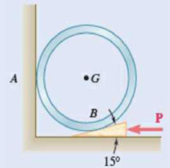
Fig. P8.64 and P8.65
(a)
Show that the slipping will occur between the pipe and the vertical wall.
Explanation of Solution
Given information:
The mass of the pipe is
The value of angle
The coefficient of static friction at all surfaces is
Calculation:
Find the weight (W) of the pipe using the relation.
Here, the acceleration due to gravity is g.
Consider the acceleration due to gravity is
Substitute 50 kg for m and
Show the free-body diagram of the pipe as in Figure 1.
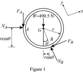
Find the friction force at point A using the relation.
Here, the normal force at point A is
Find the normal force at point A by taking moment about point B.
Substitute 490.5 N for W, 0.20 for
Find the friction force at point B
Substitute 490.5 N for W, 0.20 for
Find the normal force at point B
Substitute 490.5 N for W, 0.20 for
Find the maximum friction force at point B using the relation.
Substitute 0.20 for
The friction force at point B is less than the maximum friction force at point B.
Therefore, the slipping will not occur at point B and the slipping will occur between the pipe and the vertical wall.
(b)
Find the force P required to move the wedge.
Answer to Problem 8.64P
The force P required to move the wedge is
Explanation of Solution
Given information:
The mass of the pipe is
The value of angle
The coefficient of static friction at all surfaces is
Calculation:
Show the free-body diagram of the wedge as in Figure 2.
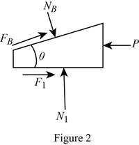
Find the normal force
Substitute 554.155 N for
Find the force P by resolving the horizontal component of forces.
Substitute 554.155 N for
Therefore, the force P required to move the wedge is
Want to see more full solutions like this?
Chapter 8 Solutions
EBK VECTOR MECHANICS FOR ENGINEERS: STA


- In figure A, the homogeneous rod of constant cross section is attached to unyielding supports. In figure B, a homogeneous bar with a cross-sectional area of 600 mm2 is attached to rigid supports. The bar carries the axial loads P1 = 20 kN and P2 = 60 kN, as shown.1. In figure A, derive the expression that calculates the reaction R1 in terms of P, and the given dimensions.2. In figure B, calculate the reaction (kN) at A.3. In figure B, calculate the maximum axial stress (MPa) in the rod.arrow_forward(Read image)arrow_forward(Read Image)arrow_forward
- M16x2 grade 8.8 bolts No. 25 C1- Q.2. The figure is a cross section of a grade 25 cast-iron pressure vessel. A total of N, M16x2.0 grade 8.8 bolts are to be used to resist a separating force of 160 kN. (a) Determine ks, km, and C. (b) Find the number of bolts required for a load factor of 2 where the bolts may be reused when the joint 19 mm is taken apart. (c) with the number of bolts obtained in (b), determine the realized load factor for overload, the yielding factor of safety, and the separation factor of safety. 19 mmarrow_forwardProblem4. The thin uniform disk of mass m = 1-kg and radius R = 0.1m spins about the bent shaft OG with the angular speed w2 = 20 rad/s. At the same time, the shaft rotates about the z-axis with the angular speed 001 = 10 rad/s. The angle between the bent portion of the shaft and the z-axis is ẞ = 35°. The mass of the shaft is negligible compared to the mass of the disk. a. Find the angular momentum of the disk with respect to point G, based on the axis orientation as shown. Include an MVD in your solution. b. Find the angular momentum of the disk with respect to point O, based on the axis orientation as shown. (Note: O is NOT the center of fixed-point rotation.) c. Find the kinetic energy of the assembly. z R R 002 2R x Answer: H = -0.046ĵ-0.040 kg-m²/sec Ho=-0.146-0.015 kg-m²/sec T 0.518 N-m =arrow_forwardProblem 3. The assembly shown consists of a solid sphere of mass m and the uniform slender rod of the same mass, both of which are welded to the shaft. The assembly is rotating with angular velocity w at a particular moment. Find the angular momentum with respect to point O, in terms of the axes shown. Answer: Ñ。 = ½mc²wcosßsinßĵ + (}{mr²w + 2mb²w + ½ mc²wcos²ß) k 3 m r b 2 C لا marrow_forward
- I have Euler parameters that describe the orientation of N relative to Q, e = -0.7071*n3, e4 = 0.7071. I have Euler parameters that describe the orientation of U relative to N, e = -1/sqrt(3)*n1, e4 = sqrt(2/3). After using euler parameter rule of successive rotations, I get euler parameters that describe the orientation of U relative to Q, e = -0.4082*n1 - 0.4082*n2 - 0.5774*n3. I need euler parameters that describe the orientation of U relative to Q in vector basis of q instead of n. How do I get that?arrow_forwardDescribe at least 4 processes in engineering where control charts are (or should be) appliedarrow_forwardDescribe at least two (2) processes where control charts are (or should be) applied.arrow_forward
 International Edition---engineering Mechanics: St...Mechanical EngineeringISBN:9781305501607Author:Andrew Pytel And Jaan KiusalaasPublisher:CENGAGE L