
Mechanics of Materials
11th Edition
ISBN: 9780137605514
Author: Russell C. Hibbeler
Publisher: Pearson Education (US)
expand_more
expand_more
format_list_bulleted
Concept explainers
Videos
Textbook Question
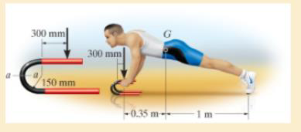
Chapter 8.2, Problem 46P
He is supported uniformly by two bars, each having a diameter of 25 mm. Assume the floor is smooth. Use the curved-beam formula to calculate the bending stress.
Expert Solution & Answer
Want to see the full answer?
Check out a sample textbook solution
Students have asked these similar questions
6. Consider a 10N step input to the mechanical system shown below, take M = 15kg, K = 135N/m, and
b = 0.4 Ns/m.
(a) Assume zero initial condition, calculate the
(i)
System pole
(ii)
System characterization, and
(iii) The time domain response
(b) Calculate the steady-state value of the system
b
[
www
K
个
х
M
-F(+)
2. Solve the following linear time invariant differential equations using Laplace transforms subject to
different initial conditions
(a) y-y=t
for y(0) = 1 and y(0) = 1
(b) ÿ+4y+ 4y = u(t)
for y(0) = 0 and y(0) = 1
(c) y-y-2y=0
for y(0) = 1 and y(0) = 0
3. For the mechanical systems shown below, the springs are undeflected when x₁ = x2 = x3 = 0 and
the input is given as fa(t). Draw the free-body diagrams and write the modeling equations governing
each of the systems.
K₁
000
K₂
000
M₁
M2
-fa(t)
B₂
B₁
(a)
fa(t)
M2
K₂
000
B
K₁
x1
000
M₁
(b)
Chapter 8 Solutions
Mechanics of Materials
Ch. 8.1 - If it is subjected to an internal pressure of p =...Ch. 8.1 - If it is subjected to an internal pressure of p =...Ch. 8.1 - The thin-walled cylinder can be supported in one...Ch. 8.1 - If the inner diameter of the tank is 22 in., and...Ch. 8.1 - Prob. 5PCh. 8.1 - 88. The steel water pipe has an inner diameter of...Ch. 8.1 - The steel water pipe has an inner diameter of 12...Ch. 8.2 - Fundamental Problems F81. Determine the normal...Ch. 8.2 - Show the results in a differential element at the...Ch. 8.2 - Determine the state of stress at point A on the...
Ch. 8.2 - Determine the magnitude of the load P that will...Ch. 8.2 - Determine the state of stress at point B. Show the...Ch. 8.2 - Determine the state of stress at point A on the...Ch. 8.2 - Determine the state of stress at point A on the...Ch. 8.2 - Show the results in a differential element at the...Ch. 8.2 - The plate has a thickness of 20 mm and P acts...Ch. 8.2 - Plot the distribution of normal stress acting...Ch. 8.2 - Also, plot the normal-stress distribution over the...Ch. 8.2 - Determine the stress components at point A on the...Ch. 8.2 - Determine the stress components at point B on the...Ch. 8.2 - If it is subjected to the force system shown,...Ch. 8.2 - Neglect the weight of the block.Ch. 8.2 - Neglect the weight of the block.Ch. 8.2 - He is supported uniformly by two bars, each having...Ch. 8.2 - Specify the region to which this load can be...Ch. 8.2 - The pins at C and D are at the same location as...Ch. 8.2 - If the force at the ram on the clamp at D is P= 8...Ch. 8.2 - Determine the maximum ram force P that can be...Ch. 8.2 - and an outer radius of 3.00 in. If the face of the...Ch. 8 - If it supports a cable loading of 800 lb,...Ch. 8 - Determine the state of stress at point E on the...Ch. 8 - Determine the state of stress at point F on the...Ch. 8 - The suspender arm AE has a square cross-sectional...Ch. 8 - If the cross section of the femur at section aa...Ch. 8 - If it has a mass of 5 kg/m, determine the largest...Ch. 8 - and is used to support the vertical reactions of...Ch. 8 - and is used to support the vertical reactions of...
Knowledge Booster


Learn more about
Need a deep-dive on the concept behind this application? Look no further. Learn more about this topic, mechanical-engineering and related others by exploring similar questions and additional content below.Similar questions
- This question i m uploading second time . before you provide me incorrect answer. read the question carefully and solve accordily.arrow_forward1. Create a table comparing five different analogous variables for translational, rotational, electrical and fluid systems. Include the standard symbols for each variable in their respective systems.arrow_forward2) Suppose that two unequal masses m₁ and m₂ are moving with initial velocities v₁ and v₂, respectively. The masses hit each other and have a coefficient of restitution e. After the impact, mass 1 and 2 head to their respective gaps at angles a and ẞ, respectively. Derive expressions for each of the angles in terms of the initial velocities and the coefficient of restitution. m1 m2 8 m1 m2 βarrow_forward
- 4. Find the equivalent spring constant and equivalent viscous-friction coefficient for the systems shown below. @ B₁ B₂ H B3 (b)arrow_forward5. The cart shown below is inclined 30 degrees with respect to the horizontal. At t=0s, the cart is released from rest (i.e. with no initial velocity). If the air resistance is proportional to the velocity squared. Analytically determine the initial acceleration and final or steady-state velocity of the cart. Take M= 900 kg and b 44.145 Ns²/m². Mg -bx 2 отarrow_forward9₁ A Insulated boundary Insulated boundary dx Let's begin with the strong form for a steady-state one-dimensional heat conduction problem, without convection. d dT + Q = dx dx According to Fourier's law of heat conduction, the heat flux q(x), is dT q(x)=-k dx. x Q is the internal heat source, which heat is generated per unit time per unit volume. q(x) and q(x + dx) are the heat flux conducted into the control volume at x and x + dx, respectively. k is thermal conductivity along the x direction, A is the cross-section area perpendicular to heat flux q(x). T is the temperature, and is the temperature gradient. dT dx 1. Derive the weak form using w(x) as the weight function. 2. Consider the following scenario: a 1D block is 3 m long (L = 3 m), with constant cross-section area A = 1 m². The left free surface of the block (x = 0) is maintained at a constant temperature of 200 °C, and the right surface (x = L = 3m) is insulated. Recall that Neumann boundary conditions are naturally satisfied…arrow_forward
- 1 - Clearly identify the system and its mass and energy exchanges between each system and its surroundings by drawing a box to represent the system boundary, and showing the exchanges by input and output arrows. You may want to search and check the systems on the Internet in case you are not familiar with their operations. A pot with boiling water on a gas stove A domestic electric water heater A motor cycle driven on the roadfrom thermodynamics You just need to draw and put arrows on the first part a b and carrow_forward7. A distributed load w(x) = 4x1/3 acts on the beam AB shown in Figure 7, where x is measured in meters and w is in kN/m. The length of the beam is L = 4 m. Find the moment of the resultant force about the point B. w(x) per unit length L Figure 7 Barrow_forward4. The press in Figure 4 is used to crush a small rock at E. The press comprises three links ABC, CDE and BG, pinned to each other at B and C, and to the ground at D and G. Sketch free-body diagrams of each component and hence determine the force exerted on the rock when a vertical force F = 400 N is applied at A. 210 80 80 C F 200 B 80 E 60% -O-D G All dimensions in mm. Figure 4arrow_forward
- 2. Figure 2 shows a device for lifting bricks and concrete blocks. It comprises two compo- nents ABC and BD, with a frictionless pin at B. Determine the minimum coefficient of friction required at A and D if the device is to work satisfactorily. W all dimensions in inches Figure 2 Darrow_forward1. The shaft AD in Figure 1 supports two pulleys at B and C of radius 200 mm and 250 mm respectively. The shaft is supported in frictionless bearings at A and D and is rotating clockwise (when viewed from the right) at a constant speed of 300 rpm. Only bearing A can support thrust. The tensions T₁ = 200 N, T₂ = 400 N, and T3 = 300 N. The distances AB = 120 mm, BC = 150 mm, and CD120 mm. Find the tension 74 and the reaction forces at the bearings. A T fo Figure 1arrow_forward5. Figure 5 shows a two-dimensional idealization of the front suspension system for a car. During cornering, the road exerts a vertical force of 5 kN and a leftward horizontal force of 1.2 kN on the tire, which is of 510 mm diameter. Draw free-body diagrams of each component and determine the forces transmitted between them. 250 A -320 B 170 D 170 -220-220- all dimensions in mm. Figure 5arrow_forward
arrow_back_ios
SEE MORE QUESTIONS
arrow_forward_ios
Recommended textbooks for you
 Mechanics of Materials (MindTap Course List)Mechanical EngineeringISBN:9781337093347Author:Barry J. Goodno, James M. GerePublisher:Cengage Learning
Mechanics of Materials (MindTap Course List)
Mechanical Engineering
ISBN:9781337093347
Author:Barry J. Goodno, James M. Gere
Publisher:Cengage Learning
Everything About COMBINED LOADING in 10 Minutes! Mechanics of Materials; Author: Less Boring Lectures;https://www.youtube.com/watch?v=N-PlI900hSg;License: Standard youtube license