Concept explainers
(a) Show that the beam of Prob. 8.41 cannot be moved if the top surface of the dolly is slightly lower than the platform. (b) Show that the beam can be moved if two 175-lb workers stand on the beam at B, and determine how far to the left the beam can be moved.
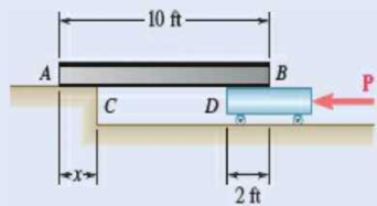
8.41 A 10-ft beam, weighing 1200 lb, is to be moved to the left onto the platform as shown. A horizontal force P is applied to the dolly, which is mounted on frictionless wheels. The coefficients of friction between all surfaces are μs = 0.30 and μs = 0.25, and initially, χ = 2 ft. Knowing that the top surface of the dolly is slightly higher than the platform, determine the force P required to start moving the beam. (Hint: The beam is supported at A and D.)

Fig. P8.41
(a)
Show that the beam cannot be moved if the top surface of the dolly is slightly lower than the platform.
Explanation of Solution
Given information:
The length of the beam is 10 ft.
The weight of the beam is
The coefficient of static friction between the surfaces is
The coefficient of kinetic friction between the surfaces is
Calculation:
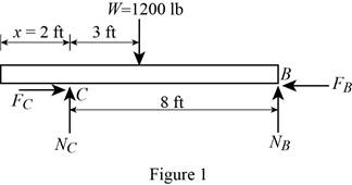
Show the free-body diagram of the beam AB as in Figure 1.

Find the normal force at point B by taking moment about end C.
Find the normal force at point C by resolving the vertical component of forces.
Find the maximum friction force at point C
Substitute 0.30 for
Find the maximum friction force at point B
Substitute 0.30 for
The maximum friction force at point B is less than the maximum friction force at point C.
The sliding is about to happen at point B.
Therefore, the beam
(b)
Show that the beam can be moved if two 175-lb workers stand on the beam at B.
Find the distance the beam moves to the left.
Answer to Problem 8.42P
The distance the beam moves to the left is
Explanation of Solution
Given information:
The length of the beam is 10 ft.
The weight of the beam is
The coefficient of static friction between the surfaces is
The coefficient of kinetic friction between the surfaces is
Calculation:
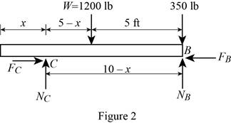
Show the free-body diagram of the beam AB as in Figure 2.

Find the normal force at point B by taking moment about end C.
Find the normal reaction at point C by taking moment about point B.
When two 175 lb workers stand on the end B:
Substitute 2 ft for x in Equation (1).
Substitute 2 ft for x in Equation (2).
Find the maximum friction force at point C
Substitute 0.30 for
Find the maximum friction force at point B
Substitute 0.30 for
The maximum friction force at point B is greater than the maximum friction force at point C.
The sliding is about to happen at point C.
Therefore, the beam
The beam will stop moving when the friction force at point C is equal to the maximum friction force at point B.
Find the friction force at point C
Substitute 0.25 for
Find the maximum friction force at point B
Substitute 0.30 for
Substitute
Therefore, the distance the beam moves to the left is
Want to see more full solutions like this?
Chapter 8 Solutions
VECTOR MECHANICS FOR ENGINEERS W/CON >B
- Please stop screenshoting ai solution,it always in accurate solve normalarrow_forwardResearch and select any different values for the Ratio of connecting rod length to crank radius from various engine models, then analyze how these changes affect instantaneous velocity and acceleration, presenting your findings visually using graphs.arrow_forwardPb 9) 4.44 bas gnibus& WX 002 grillimatul fred bail (e) For the simply supported I-beam, a load of 1000 lb in center. Find the maximum transverse shear stress. Compare your answer with the approximation obtained by dividing the shear load by the area of the web only with the web considered to extend for the full 8-in depth. - 3½ in. 12 bas in 0% to tolerabib tormi no grived in. 8 in. 38 in. 12 ½ in.arrow_forward
- Pb 12) 4.61 Draw the Mohr circle for the stresses experienced by the surface of an internally pressurized steel tube that is subject to the tangential and axial stresses in the outer surface of 45 ksi and 30 ksi, respectively, and a torsional stress of 18 ksi. yx 18 45 30arrow_forwardPb 8) 4.39 For the C-clamp shown, what force F can be exerted by the screw if the maximum tensile stress in the clamp is to be limited to 30 ksi? F 2 in. სის 3436 16 13 blos 0101 alos12 nodus 121A (s 3 in. in. 16 in. 16 web leonas OFF elson yollA (d 016 (& d of bolow-bloo ai 15912 020112LA sue) vilisub 22 bal.90 Swman a bris ctxibasqqA) laste is tools?arrow_forwardQuiz/An eccentrically loaded bracket is welded to the support as shown in Figure below. The load is static. The weld size for weld w1 is h1 = 6mm, for w2 h2 = 5mm, and for w3 is h3 =5.5 mm. Determine the safety factor (S.f) for the welds. F=22 kN. Use an AWS Electrode type (E90xx). 140 S Find the centroid I want university professor solutions O REDMI NOTE 8 PRO CAI QUAD CAMERA 101.15 Farrow_forward
- Pb 6) 4.31 do = 25 mm 4.31 What bending moment is required to produce a maximum normal stress of 400 MPa: (a) In a straight round rod of 40-mm diameter? (b) In a straight square rod, 40 mm on a side (with bending about the X axis as shown for a rectangular section in Appendix B-2)?arrow_forwardPb 13) 4.73 Find the maximum value of stress at the hole and semicircular notch. 45000 N 50 mm 100 mm 15 mm 25 mm 45000 Narrow_forwardPb 11) 4.53 Consider the 1-in solid round shaft supported by self-aligning bearings at A and B. Attached to the shaft are two chain sprockets that are loaded as shown. Treat this as a static loading problem and identify the specific shat location subjected to the most severe state of stress and make a Mohr circle representation of this stress state. 1-in.-dia. shaft 500 lb 2 in. 1000 lb 3 in. 3 in.arrow_forward
- Pb 5) 4.19 Estimate the torque required to produce a maximum shear stress of 570 MPa in a hollow shaft having an inner diameter of 20 mm and an outer diameter of 25 mm. d; = 20 mm T d = 25 mm Tmax = 570 MPaarrow_forwardQuiz/An eccentrically loaded bracket is welded to the support as shown in Figure below. The load is static. The weld size for weld w1 is h1 = 6mm, for w2 h2 = 5mm, and for w3 is h3 =5.5 mm. Determine the safety factor (S.f) for the welds. F=22 kN. Use an AWS Electrode type (E90xx). I want university professor solutions O REDMI NOTE 8 PRO CAI QUAD CAMERA 140 S 101.15 Farrow_forwardResearch and select different values for the R ratio from various engine models, then analyze how these changes affect instantaneous velocity and acceleration, presenting your findings visually using graphsarrow_forward
 Elements Of ElectromagneticsMechanical EngineeringISBN:9780190698614Author:Sadiku, Matthew N. O.Publisher:Oxford University Press
 Mechanics of Materials (10th Edition)Mechanical EngineeringISBN:9780134319650Author:Russell C. HibbelerPublisher:PEARSON
 Thermodynamics: An Engineering ApproachMechanical EngineeringISBN:9781259822674Author:Yunus A. Cengel Dr., Michael A. BolesPublisher:McGraw-Hill Education
 Control Systems EngineeringMechanical EngineeringISBN:9781118170519Author:Norman S. NisePublisher:WILEY
 Mechanics of Materials (MindTap Course List)Mechanical EngineeringISBN:9781337093347Author:Barry J. Goodno, James M. GerePublisher:Cengage Learning
 Engineering Mechanics: StaticsMechanical EngineeringISBN:9781118807330Author:James L. Meriam, L. G. Kraige, J. N. BoltonPublisher:WILEY


