
DELMAR'S STANDARD TEXT OF ELECTRICITY
6th Edition
ISBN: 9780357323380
Author: Herman
Publisher: CENGAGE C
expand_more
expand_more
format_list_bulleted
Concept explainers
Videos
Textbook Question
Chapter 8, Problem 9PP
Find the missing values for the circuit shown in Figure 8-27.
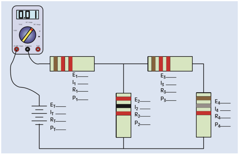
FIGURE 8-27 Combination circuit.
Expert Solution & Answer
Want to see the full answer?
Check out a sample textbook solution
Students have asked these similar questions
I need help checking if its correct
-E1 + VR1 + VR4 – E2 + VR3 = 0 -------> Loop 1 (a)
R1(I1) + R4(I1 – I2) + R3(I1) = E1 + E2 ------> Loop 1 (b)
R1(I1) + R4(I1) - R4(I2) + R3(I1) = E1 + E2 ------> Loop 1 (c)
(R1 + R3 + R4) (I1) - R4(I2) = E1 + E2 ------> Loop 1 (d)
Now that we have loop 1 equation will procced on finding the equation of I2 current loop. However, a reminder that because we are going in a clockwise direction, it goes against the direction of the current. As such we will get an equation for the matrix that will be:
E2 – VR4 – VR2 + E3 = 0 ------> Loop 2 (a)
-R4(I2 – I1) -R2(I2) = -E2 – E3 ------> Loop 2 (b)
-R4(I2) + R4(I1) - R2(I2) = -E2 – E3 -----> Loop 2 (c)
R4(I1) – (R4 + R2)(I2) = -E2 – E3 -----> Loop 2 (d)
These two equations will be implemented to the matrix formula I = inv(A) * b
R11 R12
(R1 + R3 + R4)
-R4
-R4
R4 + R2
10.2 For each of the following groups of sources, determineif the three sources constitute a balanced source, and if it is,determine if it has a positive or negative phase sequence.(a) va(t) = 169.7cos(377t +15◦) Vvb(t) = 169.7cos(377t −105◦) Vvc(t) = 169.7sin(377t −135◦) V(b) va(t) = 311cos(wt −12◦) Vvb(t) = 311cos(wt +108◦) Vvc(t) = 311cos(wt +228◦) V(c) V1 = 140 −140◦ VV2 = 114 −20◦ VV3 = 124 100◦ V
Apply single-phase equivalency to determine the linecurrents in the Y-D network shown in Fig. P10.13. The loadimpedances are Zab = Zbc = Zca = (25+ j5) W
Chapter 8 Solutions
DELMAR'S STANDARD TEXT OF ELECTRICITY
Ch. 8 - Referto Figure 8-2. Replace the values shown with...Ch. 8 - 2. Refer to Figure 8-5. Replace the values shown...Ch. 8 - 3. Refer to the circuit shown in Figure 8-2....Ch. 8 - Refer to the circuit shown in Figure 6-22. The...Ch. 8 - Refer to Figure 8-21. Assume that the resistors...Ch. 8 - A circuit contains a 1000- and a 300- resistor...Ch. 8 - Two resistors are connected in series. One...Ch. 8 - A single-phase electric motor is connected to a...Ch. 8 - The hot water for the heating system for a small...Ch. 8 - Find the unknown values in the circuit if the...
Ch. 8 - Refer to the circuit shown in Figure 8-21 to solve...Ch. 8 - 3. Find the unknown values in the circuit if the...Ch. 8 - Refer to the circuit shown in Figure 8-25 to solve...Ch. 8 - 5. Find the unknown values in the circuit if the...Ch. 8 - Find the unknown values in the circuit if the...Ch. 8 - Refer to the circuit shown in Figure 8-26 to solve...Ch. 8 - ET E1 E2 E3 E41.248V IT I1 I2 I3 I4 RT R1 R2 R3 R4...Ch. 8 - Find the missing values for the circuit shown in...Ch. 8 - Find the missing values for the circuit shown in...
Knowledge Booster


Learn more about
Need a deep-dive on the concept behind this application? Look no further. Learn more about this topic, electrical-engineering and related others by exploring similar questions and additional content below.Similar questions
- 10.8 In the network of Fig. P10.8, Za = Zb = Zc = (25+ j5) W.Determine the line currents.arrow_forwardUsing D flip-flops, design a synchronous counter. The counter counts in the sequence 1,3,5,7, 1,7,5,3,1,3,5,7,.... when its enable input x is equal to 1; otherwise, the counter count 0. Present state Next state x=0 Next state x=1 Output SO 52 S1 1 S1 54 53 3 52 53 S2 56 51 0 $5 5 54 S4 53 0 55 58 57 7 56 56 55 0 57 S10 59 1 58 58 S7 0 59 S12 S11 7 $10 $10 59 0 $11 $14 $13 5 $12 S12 $11 0 513 $15 SO 3 S14 $14 S13 0 $15 515 SO 0 Explain how to get the table step by step with drawing the state diagram and finding the Karnaugh map.arrow_forwardFor the oscillator resonance circuit shown in Fig. (5), derive the oscillation frequency Feedback and open-loop gains. L₁ 5 mH (a) ell +10 V R₁ ww R3 S C2 HH 1 με 1000 pF 100 pF R₂ 1 με RA H (b) +9 V R4 CA 470 pF C₁ R3 HH 1 με R₁ ww L₁ 000 1.5 mH R₂ ww Hi 1 μF L2 m 10 mHarrow_forward
- Expert handwritten solution onlyarrow_forwardB. For the oscillator circuit shown in frequency, feedback and open-loop gains. +10 V name the circuit, derive and find the oscillation P.Av +9 V -000 4₁ 5 mH w R₁ C₂ HH 1 με w 100 pF R₂ T R CA www. 470 pF w ww www 1000 pF HH 1μF C₁ HH 1μF Ra ww HI 4₁ 000 1.5 mH H 4 AF 000 10 mHarrow_forwardI want to check if the current that I have from using the mesh analysis is correct? I1 = 0.214mA I2 = -0.429mAarrow_forward
- I want to find the current by using mesh analysis pleasearrow_forwardI want to find the current by using mesh analysis pleasearrow_forwardR₁ W +10 V R3 +9 V C₂ R₁ CA C₁ 470 pF HH 1000 pF HH 1 με C4 1 μF 1 uF C₁ R₂ R4 100 pF Find Open-loop Jain L₁ 5 mH (a) Av=S,B={" H R₁₂ ✓ ww (b) R₁ L₁ 000 1.5 mH R₂ H 1 uF 12 10 mHarrow_forward
- A) Calculate the efficiency of the test transformer at the resistive loads (X-25%, 50%, 75%, 100%, 125% full load). B) From part (A) draw the plot (efficiency Vs power output) of the transformer. C) Discuss the plot of part (B).arrow_forwarda- Determine fH; and Ho b- Find fg and fr. c- Sketch the frequency response for the high-frequency region using a Bode plot and determine the cutoff frequency. Ans: 277.89 KHz; 2.73 MHz; 895.56 KHz; 107.47 MHz. 14V Cw=5pF Cwo-8pF Coc-12 pF 5.6kQ Ch. 40. pF C-8pF 68kQ 0.47µF Vo 0.82 kQ V₁ B=120 0.47µF www 3.3kQ 10kQ 1.2kQ =20µF Narrow_forwardUsing D flip-flops, design a synchronous counter. The counter counts in the sequence 1,3,5,7, 1,7,5,3,1,3,5,7,.... when its enable input x is equal to 1; otherwise, the counter. This counter is for individual settings only need the state diagram and need the state table to use 16 states from So to S15.arrow_forward
arrow_back_ios
SEE MORE QUESTIONS
arrow_forward_ios
Recommended textbooks for you
 Delmar's Standard Textbook Of ElectricityElectrical EngineeringISBN:9781337900348Author:Stephen L. HermanPublisher:Cengage Learning
 Electricity for Refrigeration, Heating, and Air C...Mechanical EngineeringISBN:9781337399128Author:Russell E. SmithPublisher:Cengage Learning
 EBK ELECTRICAL WIRING RESIDENTIALElectrical EngineeringISBN:9781337516549Author:SimmonsPublisher:CENGAGE LEARNING - CONSIGNMENT
Delmar's Standard Textbook Of Electricity
Electrical Engineering
ISBN:9781337900348
Author:Stephen L. Herman
Publisher:Cengage Learning
Electricity for Refrigeration, Heating, and Air C...
Mechanical Engineering
ISBN:9781337399128
Author:Russell E. Smith
Publisher:Cengage Learning
EBK ELECTRICAL WIRING RESIDENTIAL
Electrical Engineering
ISBN:9781337516549
Author:Simmons
Publisher:CENGAGE LEARNING - CONSIGNMENT
Current Divider Rule; Author: Neso Academy;https://www.youtube.com/watch?v=hRU1mKWUehY;License: Standard YouTube License, CC-BY